Maker Pro
Maker Pro

FM Pulse Counting Circuit Sounds Bad

Peter Hunt

Dec 27, 2017
10
Joined
Dec 27, 2017
Messages
10
Hi

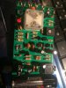
I am new here. I found this kit for a pulse counting FM. Hopefully the circuit has attached clearly.

I was very interested to see how this circuit worked because I have built a pulse counting FM receiver before (Alan Yates circuit) and it is capable
of producing a good degree of fidelity.

So when I completed this circuit the tuning is not bad and quite 'robust' BUT it sounds completely crap. All of the top end is gone.

So my question is, does this circuit contain de-emphasis, or is there some trade-off being made between reception and sound quality?

I can see a feedback loop from the audio output back into the first transistor so I am wondering if that is the offending part of the circuit. It really should not sound as bad as it does - my worst thrown together super-regen sounds better.

Cheers and seasons greetings to all.
 

Attachments

  • image.jpeg
    image.jpeg
    126.1 KB · Views: 231

Audioguru

Sep 24, 2016
3,656
Joined
Sep 24, 2016
Messages
3,656
All FM radio stations have first-order pre-emphasis (50μs in the UK) so all FM radios need matching de-emphasis.
C16, C17 and maybe others cut high frequencies in that circuit. It looks like the feedback is DC for AGC, not for audio.
 

Peter Hunt

Dec 27, 2017
10
Joined
Dec 27, 2017
Messages
10
Thanks - so if we assume that C16 and C17 are being used for de-emphasis,
if I want to reduce the amount of de-emphasis what should I do with the value of those capacitors - ? Thanks
 

Audioguru

Sep 24, 2016
3,656
Joined
Sep 24, 2016
Messages
3,656
If both C16 and C17 are making de-emphasis then it is too much and cuts highs like your stereo with its treble tone control turned all the way down. Some deaf people like maybe the designer of that circuit cannot hear the difference between 3kHz AM bandwidth and 15kHz FM.
But the resistors and capacitors have no values in your schematic so we do not know what to fix.
 

Peter Hunt

Dec 27, 2017
10
Joined
Dec 27, 2017
Messages
10
image.jpeg Thanks - I did try removing C16 and C17 and that definitely made a big difference.

I thinking of trying to build this circuit again straight onto a piece of copper clad board. I think it would probably make a big difference if a proper amplifier like a 386 is used for the audio.

I am wondering whether the circuit might benefit from an RF pre-amp.

Could someone tell me what type of
oscillator is being used? Is it a colpitts?

I am very interested with this circuit because when it works well it should be able to produce a fairly high fidelity sound.
 

Audioguru

Sep 24, 2016
3,656
Joined
Sep 24, 2016
Messages
3,656
C16 and C17 are only 150pF which is almost nothing, maybe you wrongly used 150nF? Together with R7 and R8 they cut frequencies above 226kHz which is far higher than audio frequencies. R9 and C15 produce a little less de-emphasis used in the UK so the response will be a little boosted at high frequencies.
I do not see an antenna in the circuit but I see an AM demodulator.
 

Peter Hunt

Dec 27, 2017
10
Joined
Dec 27, 2017
Messages
10
I admire your confidence :D
You would be amazed if it is set up correctly and what comes before and after it is good enough. Problem is most people try to drive a quarter watt speaker without any enclosure and then think the amp is inherently rubbish.
 

Peter Hunt

Dec 27, 2017
10
Joined
Dec 27, 2017
Messages
10
image.png image.png
C16 and C17 are only 150pF which is almost nothing, maybe you wrongly used 150nF? [I will check that] Together with R7 and R8 they cut frequencies above 226kHz which is far higher than audio frequencies. R9 and C15 produce a little less

The kit manufacture/designer claims it is a pulse counting detector - Q 4 and the three surrounding diodes. I built a similar one - the attached circuit from Alan Yates website. It sounded amazing - amazing for what it is. However the front end of that circuit was really difficult to set up right (well
It was for me) I might try taking the front end from one circuit and rest from Alan Yates design
 

Audioguru

Sep 24, 2016
3,656
Joined
Sep 24, 2016
Messages
3,656
A normal superhet FM radio has a tuned RF amplifier with gain control, an IF amplifier to give it good selectivity and a normal FM detector. It works extremely well.
 

Peter Hunt

Dec 27, 2017
10
Joined
Dec 27, 2017
Messages
10
I checked. C16 and C17 were providing filtering from outside interference from things like my laptop. But I had put the correct values in place.

I will look at R9 and C15. Though I am beginning be convinced that just because I have nothing better to do with my time, I will have a go at building Alan Yates radio again (he specifically said that he has not made much of an effort with de-emphasis - and it did sound great to my ears which always prefer lots of treble.

Cheers
 

Peter Hunt

Dec 27, 2017
10
Joined
Dec 27, 2017
Messages
10
Just as a 'learning'/student kit, it does make an interesting and accessible project.
 

Attachments

  • image.jpg
    image.jpg
    257.5 KB · Views: 133

Peter Hunt

Dec 27, 2017
10
Joined
Dec 27, 2017
Messages
10
Ok - snipped out C9 - interesting effect.

So despite a bit of hissing this little radio is beginning to be serious competition for the old super-regen.

About 10 minutes ago I stumble across the original 1967 magazine. I will upload if anyone is interested.
Cheers and Merry New Year
 

aurelZ

Jun 10, 2019
98
Joined
Jun 10, 2019
Messages
98
I build similar circuit based on ArmstrongFM2 pulse counting receiver which use 70kHz IF.
Main trick with this receiver is to hold bias of IF transistors very low
somewhere 0.6 - 0,68V.On this way transistors create saw signal which is
needed for pulse counting demodulator.
 

eric1881

Jun 1, 2020
4
Joined
Jun 1, 2020
Messages
4
I build similar circuit based on ArmstrongFM2 pulse counting receiver which use 70kHz IF.
Main trick with this receiver is to hold bias of IF transistors very low
somewhere 0.6 - 0,68V.On this way transistors create saw signal which is
needed for pulse counting demodulator.

would you please Upload the full schematic
 

eric1881

Jun 1, 2020
4
Joined
Jun 1, 2020
Messages
4
Ok - snipped out C9 - interesting effect.

So despite a bit of hissing this little radio is beginning to be serious competition for the old super-regen.

About 10 minutes ago I stumble across the original 1967 magazine. I will upload if anyone is interested.
Cheers and Merry New Year

can you please upload the full details thankyou
 

Peter Hunt

Dec 27, 2017
10
Joined
Dec 27, 2017
Messages
10
If you want a reference to a pulse counting circuit which sounds great as it is - look at Alan Yates website. He did one there which I built and which works very nicely
 
Top