Maker Pro
Maker Pro

Finishing touches on motion alarm

Electric-T

Jun 4, 2017
212
Joined
Jun 4, 2017
Messages
212
So im almost done with my motion alarm project. Ive run into a few issues. Questions really. So first off what are your thoughts on grounding multiple voltages together? (Common point for all negative conductors)
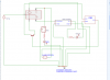
Second, the way i have it set up. I have 15v wired to a spdt relay. NC is going to a buck convertor and then to a green(ready) led and PIR. NO is going strait to a siren and will also light a red (alarm) led. My problem is i need to red led to light when the relay flips to NO but ~12v seems high. The led has a max current rating of 20 mA. Ohms law tells me that if i want to achieve 15 mA at 15v i need 8000Ω of resistance. This works on paper but i dont know if it actually works like that in practice. Is there a better way to do this? 7805 VR maybe. I will draw up a schematic for reference and post in awhile
 

Electric-T

Jun 4, 2017
212
Joined
Jun 4, 2017
Messages
212
This is what I'm thinking. How about that common "common"? Safe? Stupid? Explosive? Let me know what you think. Its already mostly built so I really don't want to back track too much. (Left out of schematic: toggle switch on AC side of PS.)
 

Attachments

  • Screenshot (8).png
    Screenshot (8).png
    20 KB · Views: 93

kellys_eye

Jun 25, 2010
6,514
Joined
Jun 25, 2010
Messages
6,514
Always amazes me how such a simple setup can be made to appear so utterly indecipherable when the schematic is drawn.....

Schematics should be readable almost at a glance - you have to STUDY yours to even make head or tails of it :p

Ever heard of 'circuit convention'?

Draw it out again with positive at the top, ground at the bottom and the signal flow running left-to-right. :rolleyes:
 

Electric-T

Jun 4, 2017
212
Joined
Jun 4, 2017
Messages
212
Always amazes me how such a simple setup can be made to appear so utterly indecipherable when the schematic is drawn.....

Schematics should be readable almost at a glance - you have to STUDY yours to even make head or tails of it :p

Ever heard of 'circuit convention'?

Draw it out again with positive at the top, ground at the bottom and the signal flow running left-to-right. :rolleyes:
Haha you got it. Whats your opinion on tying all the commons together leading to a chassis ground?
 

Audioguru

Sep 24, 2016
3,656
Joined
Sep 24, 2016
Messages
3,656
Why do you think an LED is a dead short? 15V in a 1k resistor produces a current of 15mA. 5V in a 330 ohm resistor produces 15.2mA.
But 5V in a 2V red LED in series with a 330 ohm resistor produces only 9.1mA.
The voltage across the resistor (3V) sets the current.
 

Electric-T

Jun 4, 2017
212
Joined
Jun 4, 2017
Messages
212
Why do you think an LED is a dead short? 15V in a 1k resistor produces a current of 15mA. 5V in a 330 ohm resistor produces 15.2mA.
But 5V in a 2V red LED in series with a 330 ohm resistor produces only 9.1mA.
The voltage across the resistor (3V) sets the current.
I don't understand what you're trying to say. I don't think its a dead short I thought 15 volts seemed excessive for an LED though. That's why I included the 7805 VR. Shortly after posting the question I thought of the voltage regulator. Do you think I should skip it and just run 15 volts to the LED? Its just ive never heard of a voltage that high on an LED. But if my research is correct voltage to the LED doesn't matter, its the current that's important.
 

davenn

Moderator
Sep 5, 2009
14,261
Joined
Sep 5, 2009
Messages
14,261
That's why I included the 7805 VR. Shortly after posting the question I thought of the voltage regulator. Do you think I should skip it and just run 15 volts to the LED?

yes and just use the appropriate resistor
you don't need either regulator ... the buck one nor the 5V one


Its just ive never heard of a voltage that high on an LED.

it's done all the time :)


and I really strongly agree with @kellys_eye , you need to do some serious learning of how to lay out circuit drawings ;):D
it's one thing, for you as a new comer to electronics, to get your head around quickly before your bad methods become habits ;)


Dave
 
Last edited:

davenn

Moderator
Sep 5, 2009
14,261
Joined
Sep 5, 2009
Messages
14,261
OK here is a quick lunchtime and serious tidy up of your circuit
see how much easier it is to read ?

in your original one you missed out the diode across the relay coil
and I have purposely left out the resistor values so you can use that link in my last post to work the value out

also you may or may not need a ~ 470 Ohm to 1k resistor between the PIR output and the base of the transistor
I would recommend using a 1k for a start and dropping to 470 Ohms if the relay doesn't switch reliably

alarm cct.GIF

Dave
 

kellys_eye

Jun 25, 2010
6,514
Joined
Jun 25, 2010
Messages
6,514
I considered reworking the schematic myself but lost the will to live.

@Electric-T see how much difference it makes? Can you see how much easier it is to understand? I hope you can take this onboard - it will make you a much better experimenter if you can understand your own notes! :D
 

Electric-T

Jun 4, 2017
212
Joined
Jun 4, 2017
Messages
212
I will read up and learn how to correctly draw a schematic. Thanks for the help guys
 

Audioguru

Sep 24, 2016
3,656
Joined
Sep 24, 2016
Messages
3,656
An LED is a diode that emits light. A diode can conduct a massive current which will instantly burn out a low current LED if you apply a voltage to it so a resistor in series limits the current. The datasheets for LEDs show the voltage they use then the remaining voltage is across the current-limiting resistor as I showed. Ohm's Law is used to calculate the resistor value.

You said that 15V might be too high for an LED? Then for a 2V red LED at 15mA the resistor will be (15V - 2V)/15mA= 867 ohms but you can use 910 ohms for 14.3mA. How about 100V? (100V - 2V)/15mA= 6533 ohms but you can use 6.8k for 14.4mA. The LED will have only 2V across it.

You NEVER apply a voltage to an LED so you do not need a voltage regulator, instead you need a resistor in series to limit the current.
 

Electric-T

Jun 4, 2017
212
Joined
Jun 4, 2017
Messages
212
Im making the necessary adjustments and finishing up the project. Stay tuned. I will post pictures
 

Electric-T

Jun 4, 2017
212
Joined
Jun 4, 2017
Messages
212
Finished product. A little troubleshooting left to do. Pictures shown are of when it's off, armed(green) , and triggered(red). The problem is when its first turned on it acts normally. After the pir warms up, it triggers the alarm even though its pointing strait at a wall. I will start looking into it tomorrow after work but if anyone has suggestions feel free. Ahh i love the satisfaction of finishing a project :cool:
 

Attachments

  • 1504225221107193648983.jpg
    1504225221107193648983.jpg
    104.3 KB · Views: 96

Electric-T

Jun 4, 2017
212
Joined
Jun 4, 2017
Messages
212
whoops heres the rest
 

Attachments

  • 20170831_202201.jpg
    20170831_202201.jpg
    206.3 KB · Views: 69
  • 20170831_202210.jpg
    20170831_202210.jpg
    150.4 KB · Views: 81
  • 20170831_202237.jpg
    20170831_202237.jpg
    168.4 KB · Views: 83
  • 20170831_202150.jpg
    20170831_202150.jpg
    185 KB · Views: 81

Electric-T

Jun 4, 2017
212
Joined
Jun 4, 2017
Messages
212
The motion alarm i built is having issues. I turn it on and after probably 90 seconds it triggers automatically. The alarm doesnt turn off when i hit my reset button. What is going on with this thing?
 

dorke

Jun 20, 2015
2,342
Joined
Jun 20, 2015
Messages
2,342
Wait a minute...Just going to look at my crystal ball for the answer:rolleyes:

Seriously,
Post schematics and photos etc. ;)
 
Top