Maker Pro
Maker Pro

Drop voltage on transistor base

Bigz1

Aug 12, 2017
3
Joined
Aug 12, 2017
Messages
3
Hi

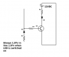
I am using a NPN transistor as a switch. I am taking the base from a LED. My problem is their is a constant voltage of 1.87v when the LED is off(1.97v when it is on). I was thinking of a zener diode of 1.9v to drop the voltage but am unable to source one. Is their an alternative way? My knowledge of electronics is very limited and appreciate any help.
 

Bigz1

Aug 12, 2017
3
Joined
Aug 12, 2017
Messages
3
My problem is the base always has voltage.
 

Attachments

  • Led project.png
    Led project.png
    16.9 KB · Views: 65

(*steve*)

¡sǝpodᴉʇuɐ ǝɥʇ ɹɐǝɥd
Moderator
Jan 21, 2010
25,510
Joined
Jan 21, 2010
Messages
25,510
Show us the circuit (the whole circuit)
 

dorke

Jun 20, 2015
2,342
Joined
Jun 20, 2015
Messages
2,342
The obvious problem is the 12v supply is connected in the opposite direction.
Change it and recheck ,like so:

Led project.png
 

Bigz1

Aug 12, 2017
3
Joined
Aug 12, 2017
Messages
3
Sorry my mistake drawing (12 v supply is right way in circuit). 12v LED is constantly on. I can't draw all the circuit. Its a UPS that's not accessible. Its remotely turned on but I want an indicator to show its status. The D1 Led is on the UPS(shows when battery is on).
 

dorke

Jun 20, 2015
2,342
Joined
Jun 20, 2015
Messages
2,342
Try measuring the on/off voltages on the junction of R1 and D1.
What led is 12V?
Another problem is ground reference between the 12V battery and the UPS.
Please show it on your drawing.
 

(*steve*)

¡sǝpodᴉʇuɐ ǝɥʇ ɹɐǝɥd
Moderator
Jan 21, 2010
25,510
Joined
Jan 21, 2010
Messages
25,510
If you completely remove the connection to the base of the transistor, does the LED stay illuminated?

If so, your first problem is one of:
  1. The transistor is connected incorrectly
  2. The transistor is PNP
  3. The transistor is damaged
  4. It is not a transistor
Do you have a part number for Q1? Values for your resistors might be nice to see also.

With the circuit you've shown the base of the transistor is effectively not connected because the rest of the circuit does nothing. However I'm assuming there is more to the circuit that you've shown. However we have no idea what it is, or even what reference you used in reading your voltages. As @dorke has said, there needs to be a ground reference, and we also need to know what the floating connections are connected to. If drawn conventionally, that diode on the far left is reverse biased, but I can't be sure that you're following any conventions in drawing your diagram.

As you can see, we're really lost without lots more information.
 

BobK

Jan 5, 2010
7,682
Joined
Jan 5, 2010
Messages
7,682
Are you saying when D1 is on the voltage is 1.97 and when it is off it is 1.87? I find that hard to believe.

Bob
 

CDRIVE

Hauling 10' pipe on a Trek Shift3
May 8, 2012
4,960
Joined
May 8, 2012
Messages
4,960
If your merely desirous of switching Q1on and off why are there two paths biasing the b,e junction?:confused:

Are these components that you're adding or are they OEM?

Chris
upload_2017-8-12_16-42-13.png
 
Top