Maker Pro
Maker Pro

Distorted audio on an old transistor radio cassette

Richard9025

May 24, 2016
205
Joined
May 24, 2016
Messages
205
Hi ,
I recently got an radio cassette , it's an VEF SIGMA 260 vintage radio , from '81 , that has distorted audio .
At LOW volume , the audio is good , but I have to stick my ear to the speaker to hear what is saying , and at HIGH volume , the sound is so distorted , u can't hear anything , only at very low volume I can hear anything , also , the cassette player works but delivers the same sound as the radio .
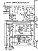
THE SCHEMATIC is attached in this thread
USER MANUAL : https://drive.google.com/file/d/0B0cJwE4DzQywM3dnWXlhR0lVbDA/view
I tested the speaker , and it doesn't have any audio distortion , I think leaky caps , like C35 (see schematic)
Some pics :
IMG_20160808_200315.jpg
IMG_20161103_103343239.jpg
IMG_20161107_205633001.jpg
IMG_20161107_205640320.jpg
IMG_20161107_205732876.jpg
IMG_20161107_205750263.jpg
PS : I have an soldering iron to solder/desolder electronics and , I can't measure capacitors with the capacitance function , my working multimeter doesn't have that function .
 

Attachments

  • VEF-sigma-260.pdf
    243.2 KB · Views: 88

HellasTechn

Apr 14, 2013
1,579
Joined
Apr 14, 2013
Messages
1,579
Before you start troubleshooting, a good thing would be to replace all electrolytic capacitors. That may solve your problem.
 

dorke

Jun 20, 2015
2,342
Joined
Jun 20, 2015
Messages
2,342
You do need a scope for this kind of problem.
I am assuming you don't have one,so a DVM may have to do.

If you have a DVM:
With volume at minimum.
Please measure the voltages marked in red relative to the blue point(GND).

BTW,
Is this a Rusky made tape?

rusky-tape.jpg
 

Richard9025

May 24, 2016
205
Joined
May 24, 2016
Messages
205
Is the black wire (red arrow) and the solder joint of it (red circle) the ground ? (The green circle marks the pozitive / negative wires of the battery compartment)
IMG_20161109_101555.jpg
The cassette recorder mechanism is made in Hungary , the rest is rusky
 

73's de Edd

Aug 21, 2015
3,622
Joined
Aug 21, 2015
Messages
3,622
Sir Richard9025 . . . . . .

If experiencing electrolytic capacitance decline the first and most likely suspect of weak and
distorted sound coming from that unit is being the PINK C35.
Next choice after that would be PINK C14

If declined capacitance is causing poor power supply decoupling check
PINK C15 and C36.

If no improvement above try using a single shielded patch cord line from the RCA type of audio output female connector found on the back of a VCR or a CD player or a DVD player and run to the yellow dot connection area for that audio input..

You are then being assured of a pristine audio signal from that point, when playing one of those items.


upload_2016-11-9_6-4-19.png


73s de Edd

.
 
Last edited:

Richard9025

May 24, 2016
205
Joined
May 24, 2016
Messages
205
If experiencing electrolytic capacitance decline the first and most likely suspect of weak and
distorted sound coming from that unit is being the PINK C35.

I think too that C35 is the suspect , it is an 10V 500uF cap . I found a 10V 470uF cap and another one16V 470uF in a newer radio , that should work well , even though they are much smaller.

If no improvement above try using a single shielded patch cord line from the RCA type of audio output female connector found on the back of a VCR or a CD player or a DVD player and run to the yellow dot connection area for that audio input..

So , to inject the audio from an rca output of an dvd player (I have one) into that yellow section ?

You should look for points 13 and 14 for GND (on board A8)

I found point 13 , but 14 I can't find (they are marked on the back of the board , some of them)
Now I try to find the points marked in red on your image , to measure the voltage on them
Front side of board A8 :
IMG_20161107_205629214.jpg
Back side of board A8 :
_20161109_214107.JPG
 

Attachments

  • _20161109_214219.JPG
    _20161109_214219.JPG
    119.7 KB · Views: 105
  • _20161109_214219.JPG
    _20161109_214219.JPG
    119.7 KB · Views: 78
  • _20161109_214107.JPG
    _20161109_214107.JPG
    502.2 KB · Views: 91

73's de Edd

Aug 21, 2015
3,622
Joined
Aug 21, 2015
Messages
3,622
Sir Richard9025

Look vewy-vewy-vewy carefully and you will see that 13 and 14 are being the SAME common ground connections that constitute a foil trace that runs around just about all of the PCB.

Specifically . . . look at your very last photo submitted, and at the right bottom corner and just come in until you meet the first foil path.
That almost encircles 3/4 of the board and also runs internally to the board and gathers scads of ground connections in all of its spread out directions.
That is also where the ground shell of my mentioned patch cord carrying in a test signal would get connected, with its tip receiving a tacked on wire to reach on, to the orange circle test input .
If you try the caps, in that replacement order, they might correct the problem with no further involve voltage tracking required.

If you end up having to find my referenced ORANGE test audio injection point, you can see that it is being a trifecta connection with the 3 common connections being to the looooong 14 pin slide/function switch connection 7 and R4 and C7 . . . .with the latter 2 connections junctions possibly being easier to locate on the circuit board.


73s de Edd
 
Last edited by a moderator:

dorke

Jun 20, 2015
2,342
Joined
Jun 20, 2015
Messages
2,342
It looks like the points marked on the schematics are not all present on the PCB.
The GND should be connected to the "-" terminal of the speaker (blue ).

rusky-tape.jpg
 

Richard9025

May 24, 2016
205
Joined
May 24, 2016
Messages
205
So , to measure the voltages easier , i marked the base (B) , collector (C) , emitter (E) , on the transistors that have a connection with the points that i need to measure , like , to measure the voltage in the point with 9,0 (top) , i need to hook the negative probe (COM) from the multimeter to the negative wire of the speaker and the pozitive probe to the emitter of the transistor 9 . The point with 5,0 -> base of transistor 7 and so on ...
Did I marked them right ? on the board , the emitter / collector / base of an transistor is marked , so it's easier to measure
rusky-tape 2.jpg
 

73's de Edd

Aug 21, 2015
3,622
Joined
Aug 21, 2015
Messages
3,622
You certainly seem to have marked all of the transistors correctly.
With only three left to have completely marked all of them I feel that you will get them correct also .
You can keep your meters negative probe at the emitter of either VT4 or VT 10 for all of your measurements .
Then you just move the meter + between all of the test points.
The VERY first and most significant reading that you can take is the point between VT 9 and VT 10.
The 9 dc supply voltage should have divided into half of its voltage at that point .
If that voltage is correct, I still think it's those two capacitors mentioned.
With C35 having had a long time capacitance decline, all the way down to approximately 3 to 5 microfarads.

73's de Edd

.
 
Last edited:

dorke

Jun 20, 2015
2,342
Joined
Jun 20, 2015
Messages
2,342
Yes,
You marked them well.

I agree with Ed about the importance of collector voltages of VT9 and VT10.
and would add the base voltage of VT2 and VT3.
 

Richard9025

May 24, 2016
205
Joined
May 24, 2016
Messages
205
So , with the tone & volume at minimum , I measured the points , with the negative probe attached to the negative wire of the speaker . (all voltages are DC , of course)
rusky-tape measured.jpg
 

73's de Edd

Aug 21, 2015
3,622
Joined
Aug 21, 2015
Messages
3,622
.

Sir Richard9025 . . . . . . .


Ahhhhhhhhhh yes, with those given voltage readings . . . .looks like you have thrown in a new variable to the situation.
They are being based on a 12.5 VDC supply voltage.
YET . . . . . . . if you analyze them proportionately and ratiometrically, they still look like good voltages for that circuit at that higher supply voltage..
BUT it does introduce a new need to define the term of " distortion " , as being applied to the sound that the unit is presently making.
I was just initially thinking of all of the errant noises that could be occurring in the audio stages.
Your given voltages now tells us that you are using the units built in power supply.
On that, you need to be referencing to the extreme left bottom corner of the schematic.

RELEVANT SCHEMATIC SNIPPET:

upload_2016-11-13_5-30-44.png

At its bottom left corner you see where the power cord is inserted.
If no power cord is plugged in, the spring contact between 2-3 routes the 6 cells of the battery
. . . .that are producing 9 volts . . . . .to supply the radio.
If you plug in the cord , the batteries are disconnected when that spring contact breaks from 3 and nudges over to 2 contact.
That then lets the radio run from the T- transformer the VD1- rectifier block and the VT1- linear series pass regulator transistor.

One little catch there . . .and that would be the required filtering capacitances associated with that circuitry.
The first C2 2000 ufd would be the normally expected smoothing capacitance, associated with levelling up the 50 or 60 cycles pulsating nodes coming out of VD1 to give you a pure smooth, ripple free DC voltage . . . . . . . . akin to that which you would be receiving from the units battery pack.
That DC purity is even further assured by the second C1 capacitor which is being tied into that resistor voltage divider of R1 and R3.
Its Miracle . . . . that separate and extra capacitance of C1 being supplied to that BASE of the regulator has an effect of then getting amplified by the gain of the transistor.
That 2000 ufd of capacitance, then becomes the equivalent of 20,000 ufd if the gain of the transistor is 10x .
or you might have a 30x gain transistor and end up with 60,000 ufd of equivalent capacitance.
This circuit enhancement, at different times, has been found to be called by two terms . . .either a capacitance multiplier or a gyrator circuit .
This is all GREEEEEAT and fine if working , BUT with all the years of ageing of those filters ,you might have had a capacitance DECLINE such that they are not filtering ANYWHERE near what is now needed.
With that power supply s pulsating ripple, creeping into or overriding into your sets audio circuitry.
If the level is minor, it shows up as a 120/100 cycle HUMMMMMM in your audio.
A progressively higher level will then start modulating your units audio and you will start getting a
" talking underwater " type of speech reproduction.
This explanation now defines yet another type of distortion that you might be hearing.


A quick way to analyze if your set is having the just mentioned power supply problem, is to put in a set of cells to then be able to evaluate its operation on the PURE DC operation produced from a battery.

Thassssit . . . .

73s de Edd


Attachments

  • upload_2016-11-13_5-48-44.png
    upload_2016-11-13_5-48-44.png
    84.9 KB · Views: 93
Last edited:

Richard9025

May 24, 2016
205
Joined
May 24, 2016
Messages
205
Yes , it is producing an " talking underwater " type of sound , and I tested it while it was hooked to the line (220V)
I don't have 6 d-cells (1,5V) (the battery compartment is for them) , but I have a 9V battery that should work like the normal 6 batteries (for a shorter time ofc) , like in this video ,
skip to 14 min
he is running an vef spidola 10 (a radio a bit older than this one) using a 9V battery
I'll try hooking a 9V battery to the battery poz/neg wires and see what happens , if something happens .
 
Last edited:

73's de Edd

Aug 21, 2015
3,622
Joined
Aug 21, 2015
Messages
3,622
Sooooooo is that the unit in question.
I hear no distorted sound . . .per se.
All of your audio on the AM band is about what I would expect as normal sound with that units speaker.

Sounds good to me . . . .particularly at sound bites :
17:37 and 18:01 and 18:14

Typical weird . . . . fading in- fading out . . . . .short wave sound at 24:43

1966-67 might be right on for THAT units dating.

31 METER would be the rough band that is encompassing the 10 mhz time reference signal.

Interesting watch !
BIG BUX to ship !

73s de Edd
 
Last edited:

Richard9025

May 24, 2016
205
Joined
May 24, 2016
Messages
205
Sooooooo is that the unit in questoin.

No , this is a video on youtube that I found . My unit , a vef sigma 260 , sounds much , much worse ( connected to line ) , i'll test it later with a 9V battery to see what it does
 
Last edited:

Richard9025

May 24, 2016
205
Joined
May 24, 2016
Messages
205
I connected it to a 9V battery and the sound is still distorted but it is a little better than when connected to line
 
Top