Maker Pro
Maker Pro

Diode question.

river_man

Jul 19, 2011
3
Joined
Jul 19, 2011
Messages
3
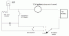
I have a circuit as illustrated in the attached image.
the 3 positions on the 3 position switch are:
1 - off,
2 - continuity test with LED, and
3 - full current to the appliance when momentary switch is pressed.

The second position is used to indicates that the circuit is complete, but pressing the momentary switch will not allow full current to the appliance.
This is what I want in position 2.

The third position allows me to press the momentary switch to provide full current to the appliance, but currently, in position 3, I lose the LED indicator unless I close the spst switch.

I would like to eliminate the SPST switch.
So my desired result in position 3 is for the LED to still be lit, and pushing the momentary switch will provide current to the appliance without having to use the spst switch.

I was thinking I could replace the switch with a diode, but I am having trouble figuring out what type/size diode to use.

If anyone could let me know what I can can do to accomplish what I'm tryng to accomplish, or point me to a location where I can find the answer, I would appreciate it.
 

Attachments

  • circuit1.jpg
    circuit1.jpg
    22.9 KB · Views: 171

TBennettcc

Dec 4, 2010
292
Joined
Dec 4, 2010
Messages
292
What about having two LEDs? One to indicate a complete circuit (i.e., voltage present), and a second to (additionally) indicate that the device is connected straight to the battery and capable of drawing (as much current as the load needs up to the current supply limit of the battery). You could even have a third LED to indicate the momentary switch is on.

Can you explain what you're trying to do here? Why you want the LED connected like that? Maybe we can figure out another way to design the circuit based on your requirements. What is the appliance? Why do you want / need a 'continuity test' function? Does that have to have the appliance in-line (in series)?

So you want the LED to light in both positions 2 and 3, but you only want the load to activate (in position 3 AND have the momentary switch pressed)? And in position 2, you do not want the load to be able to be energized?

What kind of current are we talking? Milliamps? Amps?

At present, I don't see a way to do what you described without a second LED, at the very least.

Edit: Hmm. You could probably put a diode facing the LED in place of the SPST... that should enable current to flow across the LED in positions 2 and 3, but only enable the motor in position 3... You'll need to know the max forward current (which should be whatever current the LED runs at) and the peak inverse voltage (which should be the highest voltage the battery is ever at (including charging, etc.)).
 
Last edited:

river_man

Jul 19, 2011
3
Joined
Jul 19, 2011
Messages
3
Thanks for your reply
You'll need to know the max forward current (which should be whatever current the LED runs at) and the peak inverse voltage (which should be the highest voltage the battery is ever at (including charging, etc.)).

Lets say the battery is a 12 v car battery so the max voltage is about 13 v. The current at each LED is about 25mA, but the circuit is repeated up to 48 times, so the total current to the LEDs is about 1.2A, and I'd like to use 1 Diode to replace the SPST switch.
There are so many diodes to choose from.
Is it possible to get too large of a diode?
Would this one work?
"3 AMP 100 V FAST-RECOVERY RECTIFIER" from allelectronics.com

Thanks
 

TBennettcc

Dec 4, 2010
292
Joined
Dec 4, 2010
Messages
292

river_man

Jul 19, 2011
3
Joined
Jul 19, 2011
Messages
3
Yes, those were the diodes I was thinking of, although I may just run to radio shack and see what they have in the store.

The circuit will be in parallel. The appliance could really be replaced with anything that can be connected directly to a 12 v car battery such as a 12 v trouble light.
I've attached a quick drawing of 2 in parallel to give a better idea. I do have the full schematics, but they're on another PC, so hopefully this Paint drawing will work. As mentioned before, there will be either 24 or 48 in parallel, one resistor for each LED, and likely only one momentary switch will be pressed at a time.

I'm not sure how to determine the peak inverse voltage.

Thanks
 

TBennettcc

Dec 4, 2010
292
Joined
Dec 4, 2010
Messages
292
The peak inverse voltage is the maximum reverse voltage the diode will ever see. So if your voltages never go above 14 volts or so, anything with a PIV rating of 24 volts or higher should be fine. Make sure to also look at the maximum forward current, and just be sure of your calculations, and over-rate it a bit. You should be fine.
 

Resqueline

Jul 31, 2009
2,848
Joined
Jul 31, 2009
Messages
2,848
You can replace the SPST switch with a diode but that'll change the way the (pyro firing) panel operates, disabling an important test & safety feature.
If anything, just leave the switch out.
 

TBennettcc

Dec 4, 2010
292
Joined
Dec 4, 2010
Messages
292
Maybe I missed something... what's a pyro firing panel? Is that what he's talking about? How would that change the operation?
 

Resqueline

Jul 31, 2009
2,848
Joined
Jul 31, 2009
Messages
2,848
I missed something too. Rereading the fine print I see now what river_man meant. It's not so bad but the solution still introduces one possible failure mode to keep in mind.
If the diode fails (short) then the momentary (firing) button(s) becomes live (with no warning signs) already in position 2 (test position). And 48 LED's will draw 1A btw..
The e-matches commonly used have a safe (won't fire) current of 0.2A, a will fire current of around 0.35A (differs), and have a resistance of 1.5 to 2.4 ohms.
I can't see any other uses for this type of circuit than firing pyrotechnics. Just Google the terms.
 

Attachments

  • circuit1.GIF
    circuit1.GIF
    9.2 KB · Views: 144
Top