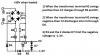
pin 7 of U3 which voltage is too high.
no, its voltage is 10V less than the +40V positive so the 10V zener diode is doing its job.
How are the other voltages on U2 and U3?
I will look at them later.
Pin 3 of U2 goes from 0 to 4V when turning Pi (with or without U2 removed)
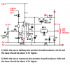
That is wrong. The output of U1 is +11/2V and feeds pin 3 of U2 though R8 and R9 which total only 29.2k so pin 3 of U2 should go from 0V to +11.2V. Maybe your voltmeter is an old low input resistance analog one instead of a modern digital one with an extremely high input resistance?
Pin 6 of U2 stays at 18V when P1 turned
During this test the BD139 is disconnected from pin 6 and R12 and C6 are disconnected from the output and connected to pin 6 instead then the opamp U2 should have a gain of 1+ [R12/(R11+RV2)]= about 30V/11.2V so that when the voltage pot is turned the output of U2 goes from 0V to 30V.
The 1N4740 zener has 10V across it.
That is good.
BD139:
Base: 40.8V
Emitter: 18V
Impossible. It is an NPN so its base to emitter voltage is 0.7V with a low current or 1V maximum with a high current, yours is 22.8V. The BD139 is destroyed or has its pins connected wrong (or both).
Oh, pin 6 of U2 is 18v and does not change with the voltage pot AND the emitter of the BD139 is also 18V. Then you wrongly connected U2 to the emitter instead of to the base?
Oh again, the base of the BD139 is 40.8V so maybe it is wrongly connected to +40.8V instead of to pin 6 of U2? Look at the datasheet of the BD139 to see which pin is which, the Chinese transistor (and the Chinese pcb) probably has a different pins layout.