Maker Pro
Maker Pro

Casio PT80 Keyboard - suspected transistor failure

Chas

Oct 26, 2017
50
Joined
Oct 26, 2017
Messages
50
Hello all,

Another electronics repair job here, hopefully something quite simple this time.

I have a little Casio PT80 keyboard instrument as seen below:
IMG_20171110_223823.jpg

When I got it, it didn't work properly because the trim pot used to adjust the tuning (accessed through a hole in the keyboard base) had been damaged. What appeared to have happened was that someone had roughly pushed a screw driver in the hole and ended up breaking the trim pot.

IMG_20171104_211100.jpg

I removed the damaged trim pot, ordered a new one one of the same specification, and then fitted that. Put the keyboard back together again, turned it on and all seemed to be working fine. The keyboard has a main voice selection for playing on the larger keys, and a drum/ rhythm section. There is a master volume control for everything, and a rhythm volume control.

Anyhow, after testing it out for a while and feeling chuffed that the little Casio was now fully functional again, I noticed a constant white noise/ static appearing. This got steadily worse, until it was so intrusive that it made using the drums/ rhythm section impossible, as that was the section that appeared to be suffering from the fault. If I turned the rhythm volume all the way down, the main voice was completely noise free. Furthermore, on first switching on the keyboard the noise was there, but only got considerably louder once the drums were triggered. After that, even when stopping the drums, the noise remained louder.

This video I took gives a good demonstration of the fault:


The keyboard is mostly analogue, almost certainly the entire drums/ rhythm section is. Being a novice when it comes to electronics, I had not much idea of where to look for the fault. However, I took a leaf out of the circuit benders handbook and simply tried grounding some of the components to see if that would have any affect. Surprisingly, I discovered that grounding some components in one section completely eradicated the noise! The main components where a 103 Capacitor, one leg of a 3 legged transistor and one of the resistors. The picture below shows the components circled in yellow, that when grounded got rid of the noise.

IMG_20171106_190454.jpg

I found that when unsoldering and lifting the leg of the C103 capacitor, the noise was gone. I though that I must have discovered the fault, so ordered a bunch of 103 capacitors. I fitted the new capacitor tonight and...


...the noise was still there. Bugger. As there was another C103 capacitor close by that also reduced the noise but not eradicated it when grounded, I decided to replace that too as I had to buy the capacitors in a pack of 10. Might as well remove it and get a bit of soldering practice in. Anyway, second 103 capacitor replaced and still no difference - the noise was still there.

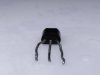
That left the T14 transistor as another likely culprit, as this also stopped the white noise when one of the legs was grounded. I unsoldered this and removed it from the board, then fired up the keyboard with the transistor missing. The white noise was now gone again and everything was working fine! By a process of elimination, I suspected that it could be the transistor that was at fault.

The problem I have now is identifying the transistor. The numbers on it are "603 3ZE".

IMG_20171116_224200.jpg

However, doing a Google search does not appear to come up with much information on it, let alone how to test it. Being a Japanese keyboard I assume this is the JIS standard of marking transistors?

Having got this far, I guess my questions are:

1. Could the transistor be the likely cause of the white noise?

2. If it is, how can I identify it and where can I find a replacement?

Obviously I know that the keyboard is noise free without the transistor fitted, however, I assume it's fitted for a reason. As such, I'd like to replace it.

Hopefully someone can kindly point me in the right direction.
 

Chas

Oct 26, 2017
50
Joined
Oct 26, 2017
Messages
50
Just to give a good idea of the circuit layout of the keyboard, here's a view showing the two main circuit boards. The green board appears to hold the master CPU, and also is where all the keys and buttons trigger via rubber membrane buttons. The brown board appears to be the analogue section, which is the drums and the accompaniment. There are even markings on the board that indicated the individual drums, i.e. SD = Snare Drum, BD = Bass Drum, CYN/ HH = Cymbals/ High Hat etc.

IMG_20171106_190344.jpg

And here's a full view of the top and bottom of the brown circuit board that hosts the analogue drums and also the audio out (and op amp).

IMG_20171117_005023.jpg IMG_20171117_005109.jpg
 

dorke

Jun 20, 2015
2,342
Joined
Jun 20, 2015
Messages
2,342
Hi Chas,

Poking around and shorting devices is a practice that should not be done
,it can be destructive and even dangerous !

The only time you can try that is if you have a schematic of the equipment and deduce(for sure!)
that a short at a specific point can be safe.

While trying to repair electric/electronic stuff ,that practice can set you back a long way in the repair process.
Consider yourself lucky if nothing was toasted.;)
 

dorke

Jun 20, 2015
2,342
Joined
Jun 20, 2015
Messages
2,342
About that transistor,
The board gives the details(photo):
It is a 2SC2603-F ,Looks like the board has a few of them.

It could be the cause of the problem,
but the fact that you puled it out and there is no noise could merely be because it is in the "sound path" ,
i.e. taking it out would prevent the noise from propagating,
it may or may not be the source of the noise.

What you should do is trace the source to it's origin with a scope or an "audio signal tracer".

IMG_20171117_005023.jpg
 

dorke

Jun 20, 2015
2,342
Joined
Jun 20, 2015
Messages
2,342
One more thing,
Can you please post a clear photo of the Tr from the legs side.
 

Chas

Oct 26, 2017
50
Joined
Oct 26, 2017
Messages
50
Hi Chas,

Poking around and shorting devices is a practice that should not be done
,it can be destructive and even dangerous !

The only time you can try that is if you have a schematic of the equipment and deduce(for sure!)
that a short at a specific point can be safe.

While trying to repair electric/electronic stuff ,that practice can set you back a long way in the repair process.
Consider yourself lucky if nothing was toasted.;)

Dorke, I totally understand and thought while doing that, that using "circuit bending" tricks would be frowned upon by real electronics experts. My bad. However, in my defence can I point out that I was only doing so while the unit was powered by 5 x batteries (I would never poke around if connected to mains voltages/ transformers). Total voltage with batteries was 7.5 VDC, thus the risk of shock was extremely low. Of course, that doesn't avoid the fact that damage can be done. As it is a low value keyboard and I have seen a number of them "circuit bent", I knew that the circuit benders generally short the capacitors/ resistors/ transistors in the analogue circuits to identify the components controlling the sounds. Additionally, Casio even helped me out by marking on the board where the "BD", "SD", "HH" etc. actually were!

Regardless, I totally understand that what I did was bad practice and it's not the sort of thing I would do when diagnosing a fault correctly (as per the Faberware food processor).

Back to the PT80:

Well spotted by seeing that the board actually states what specifications the transistors are. I missed that totally (I must pay better attention...)

Also I agree that it's wiser to trace the fault using an audio signal tracer or scope. I have neither of those unfortunately. Hence I figured that a process of elimination may be the best way forward, unless any experts could cast their eyes over the board and advise me otherwise.
 

Chas

Oct 26, 2017
50
Joined
Oct 26, 2017
Messages
50
One more thing,
Can you please post a clear photo of the Tr from the legs side.

I am assuming the mean a photo of the board from the legs side of the suspect Tr?

I took a number of pictures covering all areas of the board (that way I can get close ups). Here they are (n.b. the removed transistor was on the T14 section of the board, identified from underneath by the three empty solder holes.)

IMG_20171119_195749.jpg IMG_20171119_195757.jpg IMG_20171119_195826.jpg IMG_20171119_195852.jpg IMG_20171119_195858.jpg IMG_20171119_195933.jpg IMG_20171119_195938.jpg
 

dorke

Jun 20, 2015
2,342
Joined
Jun 20, 2015
Messages
2,342
I actually wanted the photo of transistor itself from the leg side.
The purpose is making sure there is no dirt/corrosion on and between the legs.
 

dorke

Jun 20, 2015
2,342
Joined
Jun 20, 2015
Messages
2,342
An audio signal tracer can be home made easily and cheaply in many ways.
You can use cheap magnified speaker(s),or small battery powered speakers etc.
(you may have them laying around without use anyways,or you can build one from scratch) .
All you need to add is a blocking capacitor and make a simple "probe".

Here is a simple and nice example.
the only thing I would change is make the exposed metal tip of the probe a lot smaller.

Note:
The guy is working on tube audio amps. ,that is why he is using a 400V capacitor.
for more "usual now days" amps a 100V cap should do fine.
 

73's de Edd

Aug 21, 2015
3,622
Joined
Aug 21, 2015
Messages
3,622
Sir Charles . . . . .

On your units video / audio demonstration:

I heard two types of noises, there was the random static pops which sounds like it could be a noisy transistor as it is avalanching / and / breaking down.
Then there is the pink noise . . . the rushing noise that you later had.
Plus, your adjusting the accompaniment volume slider, and quashing the offending sound, confirms that this noise is being produced or originating in the circuitry PRIOR to that control.
Your photo of your questioned transistor, revealed that it is being near the audio amplifier function of that circuit board..
I was just waiting to see . . . . as sometimes they use one junction of a transistor or zener diode as the generator of a noise source.
In this case, and looking in that immediate area, I see that they are probably using a common zener diode and it then being highly amplifying after its creation to get that mentioned noise for effects.
You are being in the corner of the circuit , that the POWER audio output stage is located . . . its function is being produced with that San -yoooooo LA4138 IC nearby.
ONE . . . . world famous " seat of the pants " by 73's de Edd, audio trouble shooting tip , that is being non destructive.
Is for you to seek out an audio amplifiers string of transistors being used.
Then you take about a .1 thru .47 ufd paper or ceramic capacitor and connect one of its leads to a clip lead that can then go to circuitry ground, its other free lead is the one that you will use as a test probe.

HYPOTHETICALLY . . . . . .

You have a . . . .three ? . . . . stage transistor amp that is sequentially processing that initially weak signal that eventually ends up at that units " accompaniment slide pot".
An optimal situation would be to have that staticy- popping sound being all present and just popping its little heart out for you.
Then you have advanced the ACC slide pot to its max noise position to hear it well.
Then you zero in on what transistors you THINK might be involved in making up that audio circuitry.
Typically you will only know that there are 3 leads involved with that transistor, its base, collector and emitter leads.
In most cases the signal comes in at the base and is amplified and leaves at the collector with the emitter being a ground or close to it.
10 % of the time they might even throw an emitter follower stage at you, where the signal still comes in the base but exits at the emitter.
The third case is so rare that we can almost handily ignore it.
NOW lets try a suspected . . . yet random stage . . . . to see if it is being a problematic stage or EVEN a part of the string related to your problem.
You will touch that caps probe lead to one of that transistors 3 leads leads . . . accordingly it is possible for that connection to create an initial pop by that connective action.
If you happened to have ended up on the emitter of a transistor that has its emitter grounded you will get no effect.
If that lead happens to be the transistors collector you would get an initial pop and there should be a DECLINE in the treble spectrum of that constantly interfering "static" that you are seeking out and MORE of a bass intonation / colorization to it, since you have thereby filtered and bypassed some of its high frequency aspect to ground.

Your capacitor should have charged up to the voltage level on that collector and if you now happen to blindly move to the next lead which might be its base, dumping that voltage level into it can be transistor ZAPPING . . . . So . . . . . after each and every probing test, you ground that probing lead to ground to discharge its capacitor.
THEN you can move to the next lead of the transistor to test.
Perchance that the next lead of the transistor happens to be the base, there would be the initial pop and then there should be an even more pronounced drop of the treble sound spectrum of that static and a perceived increase of the bass of the static. ( Due to the treble being filtered. )
By this time if you are at the third lead of the transistor and having grounded out the probe to discharge the cap and applying its probe end to the transistor and get no effect, you can suspicion that you are going ground to ground . . . . so no effect is produced.

By the time you have done this testing to three leads of a transistor, if it has no effect at all , that transistor is NOT involved with your problem, move on to another .

Say that you DID have ? number of serially arranged transistors, that do eventually feed down to your " accompaniment slide pot" the shunting in of this test cap will have the least effect on the last transistor feeding into that pot, an intermediate effect on a mid stage transistor and the most effect on the very first transistor.

And there is a possibility that the static might stop, if bypassed at a very early stage.

This testing will let you know what nearby transistors are even involved in your problem or totally eliminate some that are not even related to your circuitry.

In the interim I am still looking for some RARE schematic of this CASIO unit to REALLY see the effects generation and its actual audio flow path.

Thassssit . . . .

73's de Edd
 

Chas

Oct 26, 2017
50
Joined
Oct 26, 2017
Messages
50
I actually wanted the photo of transistor itself from the leg side.
The purpose is making sure there is no dirt/corrosion on and between the legs.

Oops, my comprehension skills let me down again...!

Here's two pictures as close up as I could get of the underside of T14 :

IMG_20171120_232743.jpg
 

Attachments

  • IMG_20171120_232810.jpg
    IMG_20171120_232810.jpg
    91.1 KB · Views: 105

Chas

Oct 26, 2017
50
Joined
Oct 26, 2017
Messages
50
An audio signal tracer can be home made easily and cheaply in many ways.
You can use cheap magnified speaker(s),or small battery powered speakers etc.
(you may have them laying around without use anyways,or you can build one from scratch) .
All you need to add is a blocking capacitor and make a simple "probe".

Here is a simple and nice example.
the only thing I would change is make the exposed metal tip of the probe a lot smaller.

Note:
The guy is working on tube audio amps. ,that is why he is using a 400V capacitor.
for more "usual now days" amps a 100V cap should do fine.

Thank you so much for that link. I will plan on purchasing those parts to make an audio signal tracer - I had assumed it was a specialist piece of equipment and had no idea it could simply be made at home. I can see how very useful it would be for me in my current situation.
 

Chas

Oct 26, 2017
50
Joined
Oct 26, 2017
Messages
50
Sir Charles . . . . .

On your units video / audio demonstration:

I heard two types of noises, there was the random static pops which sounds like it could be a noisy transistor as it is avalanching / and / breaking down.
Then there is the pink noise . . . the rushing noise that you later had.
Plus, your adjusting the accompaniment volume slider, and quashing the offending sound, confirms that this noise is being produced or originating in the circuitry PRIOR to that control.
Your photo of your questioned transistor, revealed that it is being near the audio amplifier function of that circuit board..
I was just waiting to see . . . . as sometimes they use one junction of a transistor or zener diode as the generator of a noise source.
In this case, and looking in that immediate area, I see that they are probably using a common zener diode and it then being highly amplifying after its creation to get that mentioned noise for effects.
You are being in the corner of the circuit , that the POWER audio output stage is located . . . its function is being produced with that San -yoooooo LA4138 IC nearby.
ONE . . . . world famous " seat of the pants " by 73's de Edd, audio trouble shooting tip , that is being non destructive.
Is for you to seek out an audio amplifiers string of transistors being used.
Then you take about a .1 thru .47 ufd paper or ceramic capacitor and connect one of its leads to a clip lead that can then go to circuitry ground, its other free lead is the one that you will use as a test probe.

HYPOTHETICALLY . . . . . .

You have a . . . .three ? . . . . stage transistor amp that is sequentially processing that initially weak signal that eventually ends up at that units " accompaniment slide pot".
An optimal situation would be to have that staticy- popping sound being all present and just popping its little heart out for you.
Then you have advanced the ACC slide pot to its max noise position to hear it well.
Then you zero in on what transistors you THINK might be involved in making up that audio circuitry.
Typically you will only know that there are 3 leads involved with that transistor, its base, collector and emitter leads.
In most cases the signal comes in at the base and is amplified and leaves at the collector with the emitter being a ground or close to it.
10 % of the time they might even throw an emitter follower stage at you, where the signal still comes in the base but exits at the emitter.
The third case is so rare that we can almost handily ignore it.
NOW lets try a suspected . . . yet random stage . . . . to see if it is being a problematic stage or EVEN a part of the string related to your problem.
You will touch that caps probe lead to one of that transistors 3 leads leads . . . accordingly it is possible for that connection to create an initial pop by that connective action.
If you happened to have ended up on the emitter of a transistor that has its emitter grounded you will get no effect.
If that lead happens to be the transistors collector you would get an initial pop and there should be a DECLINE in the treble spectrum of that constantly interfering "static" that you are seeking out and MORE of a bass intonation / colorization to it, since you have thereby filtered and bypassed some of its high frequency aspect to ground.

Your capacitor should have charged up to the voltage level on that collector and if you now happen to blindly move to the next lead which might be its base, dumping that voltage level into it can be transistor ZAPPING . . . . So . . . . . after each and every probing test, you ground that probing lead to ground to discharge its capacitor.
THEN you can move to the next lead of the transistor to test.
Perchance that the next lead of the transistor happens to be the base, there would be the initial pop and then there should be an even more pronounced drop of the treble sound spectrum of that static and a perceived increase of the bass of the static. ( Due to the treble being filtered. )
By this time if you are at the third lead of the transistor and having grounded out the probe to discharge the cap and applying its probe end to the transistor and get no effect, you can suspicion that you are going ground to ground . . . . so no effect is produced.

By the time you have done this testing to three leads of a transistor, if it has no effect at all , that transistor is NOT involved with your problem, move on to another .

Say that you DID have ? number of serially arranged transistors, that do eventually feed down to your " accompaniment slide pot" the shunting in of this test cap will have the least effect on the last transistor feeding into that pot, an intermediate effect on a mid stage transistor and the most effect on the very first transistor.

And there is a possibility that the static might stop, if bypassed at a very early stage.

This testing will let you know what nearby transistors are even involved in your problem or totally eliminate some that are not even related to your circuitry.

In the interim I am still looking for some RARE schematic of this CASIO unit to REALLY see the effects generation and its actual audio flow path.

Thassssit . . . .

73's de Edd

73's de Edd, wow, thank you very much for the very detailed explanation of how to carry out further fault finding, and also for explaining on how the circuitry and components appear to be working. I had to read it a few times to get it clear in my head (I'm at the beginner end of electronics if truth be told), and I think I have managed to grasp the fundamentals of what you are explaining. I will order some 0.1 ufd ceramic capacitors and get testing as per your instructions.

Really appreciate you and Dorke taking the time to help me and also to explain how these circuits are working. Thank you!
 

dorke

Jun 20, 2015
2,342
Joined
Jun 20, 2015
Messages
2,342
That is basically a toy not a real quality keyboard.
May be the PT stands for Play Toy ;)

Anyways,
The way an analog synthesizer works is much more complicated than suggested above.
It involves analog signal processing not merely a chain of amplifiers (varies filters,mixers,wave shaping ,and white noise, amplification as well).

Since there is no schematic/service manual I would approach this with trying to draw a schematic from the circuit itself.
Start from the pot. "accompanying..." backwards(the more interesting part) and forwards(will somehow get to the PA LA4138 pin-7).
It is a slow process tedious process...:(

The crackling noise Should be easier to trace.
 

dorke

Jun 20, 2015
2,342
Joined
Jun 20, 2015
Messages
2,342
From the photo The TR.
The legs are dirty,could be from the un-soldering,but I think not,it is typical of old equipment

It is hard to see If there is the same kind of dirt on the body between the legs.
It should be scraped well(gently) with an exacto knife and cleaned with rubbing alcohol.
Check visually other Trs on the board,without removing them.

IMG_20171120_232743.jpg
 

Chas

Oct 26, 2017
50
Joined
Oct 26, 2017
Messages
50
UPDATE!

First off, apologies for not updating sooner. To cut a long story short, I was away for Thanksgiving (end of November), then came back home with a bad cold. The cold developed into a chest infection that fair wiped me out for a few weeks, requiring antibiotics. Then, before I knew it Xmas was bearing down hard and I had to clear all my projects off the dining room table in preparation for the festive season. I had also ordered some replacement transistors from China, and true to their slow boat postal service, they didn't turn up until after Xmas.

What with everything else that was going on I never did get round to making an audio signal tracer or trying the trick of isolating a faulty transistor using a capacitor. Once the new transistors turned up from China, I got straight down to replacing the suspected faulty item in the little Casio. I soldered the new transitor in place, and all seemed to be going well until I needed to snip off the excess protruding legs. The side cutters I had ordered were also on the slow boat from China and had yet to arrive, so I used some larger wire cutters. Big mistake, as they didn't cut well and ended up pulling the legs from the board during the cutting action, lifting some tracks in the process. Argh! I managed to follow the traces and added some jumper wires and got the connections back. And of course, the side cutters arrived in the post the very next day. Typical! Lesson learnt, always use the correct tool and don't try and cut corners. In my defence, I only cut corners because it was a relatively low value and not a rare keyboard. I would be a lot more careful with my more valuable and rarer instruments.

The good news is, the little Casio PT80 is now fully functioning and the white noise has gone. By a process of very basic fault finding and elimination, I did manage to identify the faulty component. Of course, had I used more skilled electronics diagnostic techniques I would have identified the faulty component quicker, but hey, I got there in the end and with some help and guidance from Dorke and 73's de Edd!


That is basically a toy not a real quality keyboard.
May be the PT stands for Play Toy ;)

Anyways,
The way an analog synthesizer works is much more complicated than suggested above.
It involves analog signal processing not merely a chain of amplifiers (varies filters,mixers,wave shaping ,and white noise, amplification as well).

True, though bear in mind that many old "toy" keyboards are actually very characterful and do indeed use forms of preset analogue synthesis. Modern toy keyboards use samples or PWM techniques to generate sounds, and are little more than very basic Romplers. That's why old toy keyboards, especially Casios built prior to approx. the mid 80's, are so popular with circuit benders. It's easy to tap into various points of the analogue circuitry to "bend" or take extra control of various sonic parameters, something that is nigh on impossible with more modern sample based digital instruments.

Additionally, one of the main attractions for old low end keyboards is often their drums and rhythm sections as these often used the very same principles as used by higher end analogue drum and rhythm machines. And despite all the hype about analogue, they really do sound better than the digital/ sample based units that followed them, at least the versions that initially superseded analogue technology. As time has gone by, digital has become far better at emulating analogue and also at getting the same frequency range, likely as RAM/ ROM became cheaper along with better digital to analogue converters.

Thus, despite appearing to be little more than a toy, many of the early 80's Casios used the same technology for their rhythms/ drum sections that the professional drum machines used. And it was the drums/ rhythms that got me wanting to get the PT80 working properly again as it is so unique sounding. I have in my somewhat vast collection of keyboards some pro keyboards too, including a fully analogue (DCO) Roland JX-3P (with a KiwiTechnics upgrade that vastly expands its capabilities), a Korg DW8000 which is a digital/ analogue hybrid (digital waveforms and built in delay unit, with analogue filters and amps), and also a number of "Pro" Casios (CZ-1 and VZ-1 digital synthesizers, and an FZ-20M digital sampler that uses an analogue filter with all the digital processing). Yet some of my older home keyboards have a unique and warm sound of their own, and as mentioned, their rhythm sections especially are especially nice. They are still often sought out for their warm, Lo-Fi and kitsch characteristics by many artists and songwriters.

Enough of my ramblings! I should also add that while I had everything apart I did a small restoration job of the PT80. It had likely led a hard life and was grubby and unloved. Probably had some kids stick things into that they shouldn't as well, as per the first fault that I found (the broken trim pot). Here's how it first looked, with some black marks around the orange buttons and the ROM pack cover not fitting squarely.

IMG_20171110_223823.jpg
It was easy enough to disassemble into all its component parts:
IMG_20171112_202047.jpg
It was rather grubby inside:

IMG_20171112_203226.jpg

With all the parts removed from the plastic cases, and the plastic parts separated, they were given a good clean with soapy water:

IMG_20171112_220043.jpg

One of the orange buttons was loose, and when cleaning it, it broke off its frame. I managed to effect a repair using two part epoxy resin:

IMG_20171116_210656.jpg

It's not perfect, but it does the job and works.

The "keys" were also cleaned and reassembled. The yellowing wouldn't clean off with soapy water or alcohol. There are plastic restorer chemicals that can bring them back to more of their original bright white, though I don't mind as the yellowing gives it some character and vintage appeal.

IMG_20171116_002321.jpg

I also had to repair the battery compartment as one of the battery springs broke in two (it had been subjected to a leaking battery at some point in its life). I made a new spring section from a paperclip! It's not pretty, but it's secure and it works. Other than cannibalising another keyboard, I doubt I would find a replacement anywhere else.

IMG_20171229_002454.jpg

And here is the PT80 fully cleaned, assembled and once again fully working.

IMG_20171229_002247.jpg IMG_20171229_002303.jpg IMG_20171229_002324.jpg IMG_20171229_002351.jpg IMG_20171229_002408.jpg

And yes, the rhythm section sounds great!

Once again, thank you everyone for your help. Another electronics repair job ticked off the list, and I will be be starting another again very shortly!
 
Last edited:

dorke

Jun 20, 2015
2,342
Joined
Jun 20, 2015
Messages
2,342
Congratulations on a work well done.:)
It is nice to see the final work and the "report" of it,
wish we could see that more often.
 

Chas

Oct 26, 2017
50
Joined
Oct 26, 2017
Messages
50
It's the least I can do Dorke, especially after all the help I have had from the wise people of this forum. Additionally, I always hope that maybe the information I share might be of use to others working with the same or similar item too. Anyone else with a similar fault in an old Casio (or other keyboards) will know that there's a good chance one of the transistors are at fault. Share the knowledge and we all become enlightened!

Next project coming up very soon - an old Technics receiver unit (part of a hi-fi set up) that doesn't respond to the remote unless you put pressure on one side of the case. Odd!
 
Top