Hello,
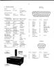
The lab I intern recently acquired a 1984 Burleigh WA-20 Wavemeter which seems to be working fine after a little patching. However, we wish to have the wavelength readings sent to a computer, and the wavemeter offers a D-sub 25 pins connector on its back.
In the instruction manuel given by the company, all the pins are assigned a designation. Error are sent as binary values, which are easy to read, but the 7-digit wavelength value is trickier. Indeed, no communication protocol is provided (Bristol instruments, defunct Burleigh successor doesn't have information concerning this issue). 4 pins are dedicated to sending BCD value, while 7 others are to send what I'm guessing to be the 7 digits (see attached file). The BCD values elude me for now.
If anyone has knowledge about communication protocols that could have been used in 1984, it would be greatly appreciated.
As for the bit of reverse engineering I've done, I probed the pins with a reading of the internal reference laser wavelength and all the D0-D6 values gave me the same voltage, as well as the decimal point. The BCDs and other non-binary values (according to my hypothesis) gave
BCD1: 2.533 V
BCD 2: 2,790 V
BCD4: 0.826 V
BCD 8: 1.064 V
D0-D6: 0.49 V
Decimal point: 0.49 V
Load: 0 V
End of Scan: 0.49
The D0-D6 values are odd, since the data to be read should be .632991, and all values were static, suggesting a weird protocol or maybe an electrical bug. Every other value was consistent with the display on the actual wave meter (errors).
Any help would be useful,
Thanks for reading,
Gabriel