Maker Pro
Maker Pro

Building a cassette interface for z80 SBC, from schematic

Harald Kapp

Moderator
Moderator
Nov 17, 2011
13,722
Joined
Nov 17, 2011
Messages
13,722
I suggest you do not concentrate on the transmission of ASCII characters for the moment. I may so happen that certain bitcodes (aka characters) when sent at the right time just by chance give the impression of a working circuit.
Focus instead on the correct operation of the circuit to:
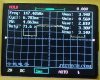
  1. Generate a 4 kHz signal when Tx = high, no signal when Tx = low. This seems to work, but you should ensure this by making a few more measurements with the scope. Use 2 traces, one for Tx, one for the audio output to check whether the above logic works correctly. You do not need a computer to send characters for this. A simple low frequency square wave (150 Hz equiv. to 300 bd) on Tx will suffice.
  2. Decode the signal from 1. into a corresponding 0/1 data stream, cf. my post #18.

You should also, as a very first step, verify the correct operation of the USB/TTL cable works correctly without this circuit, see also post #18.
 

Joe Lyman

Dec 19, 2017
22
Joined
Dec 19, 2017
Messages
22
Sorry for the long delay; the holidays plus waiting for parts are to blame. I obtained some more resistors and put the 10k on IC2 R5&6, and IC3 R8. I left the 8k2 resistors in place at U1B R2, R9, R10, and R11, and put the 100k at R1. These changes were to make the circuit more like the original schematic.

I removed the USB->TTL entirely from the equation as you recommended in posts #18 and #21. As requested, I created a 150hz tone generator, and used it as the input for IC2 pin 4. Image P1 shows the output of this new testing addition.

I tested the 4khz signal by itself, P2. As expected, when TX is high (and it is idle high with a TTL connection) then a 4hkz tone is generated. When it drops low, there is no tone. For all the rest of the tests below, I had the 150hz tone attached and running.

P3 shows the signal on IC2 pin 3.
P4 shows the audio signal out at U1A pin 1, after the capacitor.
P5 shows the audio signal in at U1B pin 6, after the capacitor.
P6 shows the output at U1B pin 7.
P7 shows the signal at Q1 pin 1 collector.
P8 shows the signal at IC3 pins 6/7.
P9 shows the output at IC3 pin 3.

You mentioned in post #4 that the voltage looked too low at the Q1 collector. I noticed that R1 seemed to affect that; when I reduced R1 the voltage went down, at Q1 pin 1, when I increased R1, the voltage went up at Q1 pin 1.

I put a 220k resistor at R1, and was able to get my 150hz wave back out at IC3 pin 3, which you can see in P10. But, the wave does not look the same. If I tweak RV2 I can make the off portion of the cycle wider or more narrow before I lose the wave, but not significantly. I haven't tried higher values at R1 yet.

P1_150hz-signal.jpg P2_4khz-noinp-IC2p3.jpg P3_IC2p3-winp.jpg P4_U1Ap1.jpg P5_U1Bp6.jpg P6_U1Bp7.jpg P7_Q1p1.jpg P8_IC3p6-7.jpg P9_IC3p3.jpg P10_IC3p3-220kR1.jpg
 
Last edited:

Harald Kapp

Moderator
Moderator
Nov 17, 2011
13,722
Joined
Nov 17, 2011
Messages
13,722
I think the Schmitt Trigger is working incorrectly. Picture 6 shows the output of U1B being high when no input signal is present. This drives Q1's collector to low (pic. 7) which constantly trigggers IC3.
As I understand the circuit, IC3 should be triggered by an incoming signal, otherwise IC3 should sit idle. Try a 10 k pot in place of R10, then adjust such that the output of U1B is low with no input signal present.

By the way, your scope images are helpful, but they'd be even more useful if you could display 2 traces at once (is that a dual chanel scope?). E.g. input to U1B and output from U1B. Having input and output of a circuit side by side makes it most often easier to understand what's going on.
 

Joe Lyman

Dec 19, 2017
22
Joined
Dec 19, 2017
Messages
22
Harald said:
Picture 6 shows the output of U1B being high when no input signal is present.
I'm not sure I entirely understand, since the 4khz signal is always present as a carrier. Should the output of the Schmitt trigger be low without the 150hz and with the 4khz, or should I see the 4khz signal coming out of the Schmitt trigger, or should the Schmitt trigger be high with just the 4hkz signal?

I put the 10k pot at R10, and I was able to adjust it to basically eliminate the 4khz signal after the Schmitt trigger. Photo attached of the new signal (with 150hz connected) coming out of U1B pin 7. The thing is, with that adjustment, and only the 4khz signal coming in, it is idle high. If I unplug the 4khz signal, it drops low. I can also adjust it to keep the 4khz signal coming out of U1B pin 7.

I think I probably need to read a bit more, and build a Schmitt trigger by itself, to make sure I understand it.

Harald said:
(is that a dual chanel scope?)
Unfortunately it's only a very cheap single-channel scope. I hope to purchase a 4-channel scope with more bandwidth at some point, when budget allows. They look wonderful to use.
 

Attachments

  • P1_U1Bp7-w10kpotR10.jpg
    P1_U1Bp7-w10kpotR10.jpg
    23.9 KB · Views: 99

Joe Lyman

Dec 19, 2017
22
Joined
Dec 19, 2017
Messages
22
In practice, it seems that IC2 produces a 4khz tone at all times, until it gets input from J1 pin 1 (IC2 pin 4, reset), which causes the 4khz tone to stop. I may be using the wrong terms, but would that make it a 4khz carrier tone? Reading on the designer's website, it appears that the 4khz tone is perhaps supposed to make it through the Schmitt trigger and get eliminated (continually held high) by the re-triggerable 300us monostable circuit.

That's just me trying to understand the designer's description of the circuit. It does appear that the schmitt trigger can be used to filter out that 4khz signal, but then if you have it filtered out at U1B pin 7, what purpose does the rest of the circuit serve?
 

Harald Kapp

Moderator
Moderator
Nov 17, 2011
13,722
Joined
Nov 17, 2011
Messages
13,722
I'm not sure I entirely understand, since the 4khz signal is always present as a carrier.
Nay, it's not. When the Tx input is low, IC2 will not generate a signal. With Tx = high IC2 will generate the 4 kHz tone.
Should the output of the Schmitt trigger be low without the 150hz and with the 4khz, or should I see the 4khz signal coming out of the Schmitt trigger, or should the Schmitt trigger be high with just the 4hkz signal?
The Schmitt Trigger serves to regenerate a clear signal only.
So with Tx = low, no 4 kHz tone is generated and teh output of the Schmitt Trigger should be low.
With Tx = high, a 4 kHz tone is generated and should also show at the output of the Schmitt Trigger.
I put the 10k pot at R10, and I was able to adjust it to basically eliminate the 4khz signal after the Schmitt trigger.
That's not what I intended. Adjust the pot such that without input to the Schmitt Trigger (Tx = low) the output of the Schmitt Trigger is low, too. Then with active input to the Schmitt Trigger (Tx = high) the 4 kHz tone should be present at the output of the Schmitt Trigger, too.
 

Joe Lyman

Dec 19, 2017
22
Joined
Dec 19, 2017
Messages
22
Thanks for that clarification on the Schmitt trigger, I appreciate you patience as I learn all this stuff. So, the Schmitt trigger takes the audio and cleans it up, then the 555 monostable re-triggerable removes the 4khz signal leaving the original signal, I believe.

I'm not sure this is an ideal source, but this page talks about TTL serial communication. It appears that TTL serial, which the circuit I'm working on uses, is idle high. The result, which I'm seeing, is that there is a constant 4khz tone coming out at J2 pin 1 (and in at J3 pin 1 when looping back) which is eliminated (quiet) when characters are received.

Of course, that doesn't have much, electrically, to do with this circuit... it's just an inversion. Either way, what goes in ought to come out the same, which is the goal.

Harald said:
That's not what I intended. Adjust the pot such that without input to the Schmitt Trigger (Tx = low) the output of the Schmitt Trigger is low, too. Then with active input to the Schmitt Trigger (Tx = high) the 4 kHz tone should be present at the output of the Schmitt Trigger, too.
I adjusted things so that: 1) U1B pin 7 is low with no input to the trigger; and, 2) U1B pin 7 produces a clean 4khz wave with the audio coming at at J3 pin 1 (see photo P1).

But take a look at photo P2. This is the output of U1B pin 7 when the 150hz tone is turned on. Shouldn't this one look more like P3 (which is the output of IC2 pin 3 tested again just now)?
P1_U1Bp7-w10kR10-4konly.jpg P2_U1Bp7-4kand150hz.jpg P3_IC2p3.jpg
 

Joe Lyman

Dec 19, 2017
22
Joined
Dec 19, 2017
Messages
22
I think I'm going to set this project aside, and focus on learning more essentials. I'm sincerely grateful for all your help, and I'm actually glad this schematic didn't work right away for me, since it's forcing me to take an approach of learning instead of just doing. Thank you!
 

Harald Kapp

Moderator
Moderator
Nov 17, 2011
13,722
Joined
Nov 17, 2011
Messages
13,722
TTL serial communication
This describes the UART protocol, the same you are using (shows up as COM1 etc. on the PC)
TTL refers to the voltage level 0V...5V), the one which you are using. This is only to distinguish it from e.g. RS232 which uses the same protocol but different voltages. For the time being do not worry about these details, stick to your TTL based design.

there is a constant 4khz tone coming out at J2 pin 1 (and in at J3 pin 1 when looping back) which is eliminated (quiet) when characters are received.
Right, the idle signal is high for the UART protocol used, therefore there is a 4 kHz tone.
When characters are transmitted these are encoded as a sequence of 1s and 0s or logic high and logic low, the sequence of which encodes the character. Therefore any character is represented by a unique sequence of 4kHz tone and no tone.

P1 looks o.k.
P2 and P3 use different time scales. I recommend you use the same time scale (x-axis) to make comparison of the screenshots easier. When you set the scale for P2 to 1ms/div, too, the signal should look similatr to P3.
Shouldn't this one look more like P3 (which is the output of IC2 pin 3 tested again just now)?
Ideally these signals should be identical. However, the slight difference should be of no concern here. It is more important that the output of IC3 shows the 150 Hz signal as expected. The UART protocol is asynchronous, meaning there is no clock signal accompanying the data. The protocol is therefore made comparatively robust against timing errors introduced by the circuit (as long as these errors are within certain limits, of course). At 300 bd each bit takes 3.3 ms. A timing error of 1 % translates to 33 μs, a comfortable margin for error.

I think I'm going to set this project aside, and focus on learning more essentials.
Learning the essentials is a good idea. Would you care to make one last test before putting this experiment aside? I think you (we) are almost finished. Please try to transmit and receive characters with the circuit as modified. I wouldn't be astonished if it works now.
 

Joe Lyman

Dec 19, 2017
22
Joined
Dec 19, 2017
Messages
22
I think you're right about being close. I connected up the USB->TTL and it transmits one character per keystroke, but the characters are garbled.

What I'd like to do is make sure I understand the various components of this circuit (the tone generator, the Schmitt trigger, the monostable), build them individually, and make sure I understand how the function and how to modify them. I'm curious about adding an inverter (I have some 7404's around) so that it's silence with a tone when transmitting, to see if the inverter can help the signal, and just out of curiosity.

I'll come back here and report, in this post or a new one, after I work on it a bit more. Thanks!
 

Joe Lyman

Dec 19, 2017
22
Joined
Dec 19, 2017
Messages
22
I feel foolish... but the circuit is working! I was looking at the scope, and the spike at the beginning of the signal that you can see in post #22 P4 was bothering me. It seemed like it was being magnified throughout the last two parts of the circuit, and messing up the signal.

I thought it might be caused by a capacitor- and keep in mind that I'm pretty new at all this- so I looked at my capacitors. On the breadboard I had used 0.1uF polarized capacitors at C10 and C11, the schematic asks for non-polarized. Still, I had tried non-polarized on my soldered version, and that didn't work, so I wasn't thinking about it.

So, I changed C10 and C11 out for some 0.1uF ceramic non-polarized capacitors that I recently got in the mail, and presto, the signal looked much better (no more spike at the beginning), and even more importantly, with all of the pots adjusted right, it functions perfectly!

Now I need to see if I can salvage/modify the soldered prototype board version, or if I need to re-do it now with the setup that we have going (including the pot at R10).

Thanks for all your help in getting this working properly, and even more importantly, for your help in actually understanding the circuit and the parts!
 

Joe Lyman

Dec 19, 2017
22
Joined
Dec 19, 2017
Messages
22
For the sake of the thread, here's a summary of the changes that ended up working:
  • 220k resistor at R1 (not needed! just found while looking at the breadboard that I had put the 100k back at R1)
  • 8k2 resistors at R2, R9, and R11
  • 10k potentiometer at R10
  • 0.1uF non-polarized ceramics at C10 and C11 (already in the schematic)
Looking at the prototype board, I think I can de-solder the series of resistors that I had at R1 and put in a 220k, and de-solder R10 to put in a potentiometer. R2,R9, and R11 I'll leave alone for now, but I can de-solder those if needed as well. I'm going to remove the larger,non-polarized green 104J/100V capacitors I have a C10 and C11 and put in the smaller 104's that I used on the breadboard in post #31.
 
Last edited:

Joe Lyman

Dec 19, 2017
22
Joined
Dec 19, 2017
Messages
22
The prototype, re-worked, also functions properly! I've attached a photo of my desk, which includes the two z80 SBC's I'm currently working on, the breadboard version of the 150hz tone generator and the UART-to-Cassette interface we've been working on, as well as the re-worked prototype board version, now functioning.

Thanks for all your help, I'm able to move forward on the larger project now!
cassette_z80_project.jpg
 

Harald Kapp

Moderator
Moderator
Nov 17, 2011
13,722
Joined
Nov 17, 2011
Messages
13,722
Glad it works. Good luck with your forthcoming projects.
 
Top