It's rather well described e.g.
here.
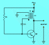
It's being said that C1 in the diagram is discharged by R1.
discharge can be to Vcc, too. Note the little dots at the transformer? Those are not dead flys
")
, they indicate the start of the winding.This means that they have the same polarity when the transformer is operating. The dot on the right side is towards Vcc, the dot on the left side is towards C1. Therefore when a current flows through the transformer's right side from Vcc towards the transistor, the connection to C1 will be positive, too.
Connecting both sides of a capacitor to the same (or a similar) potential will discharge the capacitor.