Maker Pro
Maker Pro

Amplifier Potentiometer Replacement

Blake94

Apr 22, 2017
9
Joined
Apr 22, 2017
Messages
9
Hello.

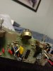
This is my first post here. I have a sunn stagemaster guitar amplifier, built some time in the early 80s. The amplifier has two output channels, A and B, each with a knob adjusting the output wattage from 1 watt to 120. Unfortunately, the shaft for the A channel potentiometer was broken clean off some time before I acquired the amp. I would like to replace it, but I have no idea which part to get to replace it. I would like to have the part before I take apart my amp and am ampless haha. All I know about the pot (if it is a pot and not a rotary switch) is that it has 12 different positions. I have been able to acquire a schematic for the amplifier, which I have attached. I have no idea how to read electronics schematics though, so I have no clue where the pertinent information lies in the document. I've tried calling around my city, and the only place that might be able to do it would charge me more than I paid for the amp in the first place. Any help here would be much appreciated. Thank you.
 

Attachments

  • Stage Master (2).PDF
    136.7 KB · Views: 84

Harald Kapp

Moderator
Moderator
Nov 17, 2011
13,725
Joined
Nov 17, 2011
Messages
13,725
The volume adjustment should be these potentimeters (from page 3):
upload_2017-4-22_20-28-25.png
Unfortunately the value is veeeery haaard to read. Could be 100kΩ - or not. When you open the amplifier, you usually find the value and the characteristic (linear or lagarithmic) written on the potentiometer housing.

The 12 different positions are possibly achieved by a mechanical snap mechanism of the knob. I've not seen potentiometers with latching positions before.
 

Alec_t

Jul 7, 2015
3,590
Joined
Jul 7, 2015
Messages
3,590
Welcome to EP!
The only gain controls shown in the schematic are normal (audio taper?) pots, not multi-way switched ones. The 12 positions are presumably defined by detents. Can you determine if those are internal or external?
Pots with internal detents are available.
 

Blake94

Apr 22, 2017
9
Joined
Apr 22, 2017
Messages
9
I guess my only recourse here is to actually open up the amp and get at the part itself. Darn. And if it's like the B channel adjuster it feels like it has internal detents. I've attached a picture of the faceplate of the amp, just for kicks.
 

Attachments

  • IMG_20170422_145611.jpg
    IMG_20170422_145611.jpg
    203.2 KB · Views: 88

hevans1944

Hop - AC8NS
Jun 21, 2012
4,880
Joined
Jun 21, 2012
Messages
4,880
Did anyone notice that the (almost illegible) schematic shows two mechanically ganged pots on a common shaft? Well, that's how I interpret the dashed lines from one wiper to the the other wiper. Your mileage (or kilometers) may differ.
 

davenn

Moderator
Sep 5, 2009
14,262
Joined
Sep 5, 2009
Messages
14,262
Did anyone notice that the (almost illegible) schematic shows two mechanically ganged pots on a common shaft? Well, that's how I interpret the dashed lines from one wiper to the the other wiper. Your mileage (or kilometers) may differ.

yes exactly !!
 

Blake94

Apr 22, 2017
9
Joined
Apr 22, 2017
Messages
9
In response to hevans, yes there are a couple pots on a common shaft in a couple instances. Thankfully the pot I need replacing isn't one. I opened up the amp and was able to get to the affected pot. I'm just not sure what kind exactly it is. It says 10kk so does that mean 100kΩ? I've attached a picture. Also, it contains internal detents for 12 positions.
 

Attachments

  • IMG_20170423_013910461.jpg
    IMG_20170423_013910461.jpg
    175.7 KB · Views: 88

Alec_t

Jul 7, 2015
3,590
Joined
Jul 7, 2015
Messages
3,590
So, it's R72. I reckon 10kk means 10k. On the schematic the text appears to read "10kA". Whether or not the "A" means logarithmic or linear is debatable, since A/B have not been used consistently by all manufacturers. Logarithmic would seem more appropriate in this application.
As it's not a ganged pot that makes replacement easier. Hopefully you can find a suitably sized one with an appropriate splined shaft.
 

Blake94

Apr 22, 2017
9
Joined
Apr 22, 2017
Messages
9
Ok. Thanks for all the help. I have one more question. Would I be able to get away with using a 10k audio taper pot without the detents? They're proving very difficult to find.
 

Alec_t

Jul 7, 2015
3,590
Joined
Jul 7, 2015
Messages
3,590
That would work, if you are happy without the detents. Perhaps you could Mcgyver some externally?
 

hevans1944

Hop - AC8NS
Jun 21, 2012
4,880
Joined
Jun 21, 2012
Messages
4,880
Below is a close-up image of the OUTPUT POWER controls. These are allegedly two 12-position detented controls, yet the markings on the panel only show eleven detent positions, namely: 1W, o, 5W, o, 25W, o, 50W, o, 90 W, o, and 120W. The detent positions with dots, intermediate between the numbered power positions, are not known but presumably follow some sort of audio or logarithmic taper function.

upload_2017-4-23_23-2-44.png
Since one of the two controls is still operational, it should be possible to remove it and measure the resistance between the wiper arm and either end of the control, for each of the eleven positions labeled on the front panel. With this information in hand, it should be possible to substitute a small 12-position SP12T wafer switch with appropriate valued resistors between each position.
 

Blake94

Apr 22, 2017
9
Joined
Apr 22, 2017
Messages
9
Hevans, you're right. It's 11 I miscounted. Still, even though 11 detent pots are easier to come by, I can't find any that would fit here. I'll keep looking, but I have ordered a 10k audio taper pot without detents. Right now I'll just settle for functional.
 

hevans1944

Hop - AC8NS
Jun 21, 2012
4,880
Joined
Jun 21, 2012
Messages
4,880
Functional is good.

However, rotary wafer switches with twelve positions are common. Many have mechanical stops that can be positioned to select from two to eleven positions, or if continuous rotation is desired, twelve positions. It should be a relatively trivial exercise to solder ten fixed resistors between adjacent poles of the switch, thereby implementing a "potentiometer" with eleven tapped positions. You could even do this for both the A and B OUTPUT POWER controls, discarding the original detented potentiometers in favor of your "custom" controls. If it were my amp I think I would prefer it that way. Easy to customize the "taper" by selecting appropriate resistors, easy to maintain because no special components are required. YM(or kms)MV.
 

Blake94

Apr 22, 2017
9
Joined
Apr 22, 2017
Messages
9
True. But I'm still a relatively broke college student and the pot only cost me 4$ with shipping (truth be told, if I could have afforded any other amp, I would have bought it). It arrived today and I soldered it in, and everything works fantastically. The 10k audio taper pot was definitely the way to go. Even though it doesn't have the detents, it works exactly as it should and I'm overjoyed to have this working. Thanks to everyone who helped me out here.
 

hevans1944

Hop - AC8NS
Jun 21, 2012
4,880
Joined
Jun 21, 2012
Messages
4,880
Good job! I am not sure why there even is "OUTPUT POWER" control unless it's possibly to protect speakers with lower wattage capabilities.
 

Blake94

Apr 22, 2017
9
Joined
Apr 22, 2017
Messages
9
Without going into too much guitar stuff, the wattage output is to change how easy it is to make the amp distort. The higher the output, the louder you can be without distorting.
 

hevans1944

Hop - AC8NS
Jun 21, 2012
4,880
Joined
Jun 21, 2012
Messages
4,880
Ha! A few years ago my wife's youngest son formed a garage band in (where else?) my detached garage. They couldn't afford much in the way of guitars, or amps, or speakers, or effects boxes (stomp boxes) etc. So they settled for LOUD.

I must confess that I didn't really appreciate their efforts, which sounded more like raucous noise instead of music to my ears, but hey, these teenagers needed an outlet for their not-so-suppressed anger at being trapped between adolescence and Medicare, and pretty much powerless to do anything about it. They had a lot of fun, the four of them jammin' together and probably scaring the hell out of the neighbors, only one of whom had the temerity to complain about the noise. But at least the cops never showed up to shut them down, a distinct possibility given the volume of sound produced. I don't think they EVER worried about distortion. In fact, distortion seemed to be the goal of their efforts.
 
Top