Maker Pro
Maker Pro

6v inverter circuit

vinod chandran

Jun 21, 2011
192
Joined
Jun 21, 2011
Messages
192
Hi all,
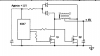
Somebody please help me to find a 6v to 220v inverter circuit. All i need to light a 11w CFL from a 6v 4.5Ah battery.
-Vinod chandran
 

davenn

Moderator
Sep 5, 2009
14,260
Joined
Sep 5, 2009
Messages
14,260
hi vinod
did you try putting "6v to 220v inverter circuit" into google
there are dozens of hits many with circuit diagrams :)

Dave
 

vinod chandran

Jun 21, 2011
192
Joined
Jun 21, 2011
Messages
192
Hi davenn,
Thank you. I just found a simple circuit but it is in 12v supply. I am attaching the image. Please look. I just tested it and it is working well with 12v battery. So What changes do i need to connect this circuit with 6v battery?. I know i need to change the transformer into 6-0-6 .Battery Ah is 4.5. Please help me.
 

Attachments

  • TO FORUM.jpg
    TO FORUM.jpg
    56.1 KB · Views: 3,262

duke37

Jan 9, 2011
5,364
Joined
Jan 9, 2011
Messages
5,364
You will need to change the transformer as you say.

6V will be insufficient to turn the fets fully on so the chip should be fed from two diodes connected to the fet drains. There will almost certainly be enough voltage to get it started.
Put an electrolytic on the 4047 supply - you should have this on the 12V circuit also.
 

vinod chandran

Jun 21, 2011
192
Joined
Jun 21, 2011
Messages
192
Hi duke37,
Thanks a lot. But i can't understand your idea. So please draw a diagram of your idea.
 

duke37

Jan 9, 2011
5,364
Joined
Jan 9, 2011
Messages
5,364
You should have an electrolytic capacitor on the 6V input since the inductive current will go in both directions under light load.

The 4047 should have a smooth supply.
 

Attachments

  • vinod.png
    vinod.png
    3.8 KB · Views: 993

vinod chandran

Jun 21, 2011
192
Joined
Jun 21, 2011
Messages
192
Hi duke37,
Thank you. Due to the language problem i am attaching an image of what i understood from your image. Please correct if any errors found.
 

Attachments

  • To duke.jpg
    To duke.jpg
    49.4 KB · Views: 812

duke37

Jan 9, 2011
5,364
Joined
Jan 9, 2011
Messages
5,364
You need a capacitor (10uF?) across the 4047 to give a smooth supply or it may get false triggering from the large currents elsewhere in the circuit.

The fets seem to be upside down. They should be source to ground, drain to transformer.
 

vinod chandran

Jun 21, 2011
192
Joined
Jun 21, 2011
Messages
192
Hi duke37,
Thank you for the reply. Let me try your idea. I've ordered a 6-0-6 3A transformer at my local winding shop. If this experiment is success, then i am able to make an inverter in 780 INR(14$)
 

vinod chandran

Jun 21, 2011
192
Joined
Jun 21, 2011
Messages
192
Out put voltage is low

Hi all,
I tried this small inverter circuit (plz look image). But the out put is 66v AC. The transformer in this circuit is from an old 600VA ups and it's amperage is unknown. Any way when connecting this transformer to 230AC , i got a 6.5v AC in secondary. So i connect this to my circuit. Somebody please tell what is wrong with this circuit and how to fix this.
-Vinod
 

Attachments

  • Capture_056.jpg
    Capture_056.jpg
    45.9 KB · Views: 818

Harald Kapp

Moderator
Moderator
Nov 17, 2011
13,722
Joined
Nov 17, 2011
Messages
13,722
My guess:
Your circuit oscillates in the kHz range. The transformer is probably designe dfor 50...60 Hz operation. Due to the high frequency the current through the transformer will not rise enough to deliver the power needed to drive 230 V at the output.

Reduce the frequency of the MV to 50...60 Hz.

Also note that the energy stored in the transformer duricng Q1's on-time needs to be bleeded when Q1 is turned off. Otherwise a high negative voltage will occur at Q1's collector. Put a diode paralel toi the transformers switched winding, cathode to P1, anode to P2.

Harald
 

Harald Kapp

Moderator
Moderator
Nov 17, 2011
13,722
Joined
Nov 17, 2011
Messages
13,722
By the way: I merged your two threads for the same topic. Please stay within one thread as long as the topic doesn't change. Only open a new thread for a new topic.

This makes life easier for all of us.

Harald
 

vinod chandran

Jun 21, 2011
192
Joined
Jun 21, 2011
Messages
192
Hi Harald Kapp,
First of all let me say thanks to you for giving a very helpful reply. I am sorry for posting this as two threads. I thought that posting as a separate thread will give more attention and replays. Any way let me try your idea. Thank you once again.
 

vinod chandran

Jun 21, 2011
192
Joined
Jun 21, 2011
Messages
192
Hi Harald Kapp,
Your idea is not working. I just reduced the frequency. This is the component value.
R1= 1.5K, R2= 100K, C1= 1uF. An online frequency calculator shows me that when using these
components, the result will be-
T1 High output(sec) =0.0703395
T2 Low output (sec) =0.0693
T1+T2 Period (sec) =0.1396395
Frequency (Hertz) =7.1464019851116625
Duty Cycle (percent) =50.37220843672456.
And the output is still 73v AC. then i connect a 1N4007 into the transformer as you said. then output
voltage become low. What to do?.
 
Top