Maker Pro
Maker Pro

5v from 12v is this viable?

Audioguru

Sep 24, 2016
3,656
Joined
Sep 24, 2016
Messages
3,656
In the Li'l Gem circuit R2 the source resistor is what sets the gain of the Jfet correct? and R1 acts as a filter?
The Little Gem MII project does not say R1, R2 etc. The Jfet (it is not a Mosfet) is a follower with a gain of 1. The source resistor should be 10k ohms to provide a suitable bias voltage. What is R1? If R1 is the input 1.5M resistor then it is not a filter, it biases the gate of the Jfet at 0V.

Since I'm running it from a system that gets charged this intended version the efficiency doesn't matter to me as long as it doesn't burn up. Future versions however will likely be run from six AA batteries(9v) and it will be an issue so using an IC in that case should gain some efficiency correct?
An IC to do what? A 7809 voltage regulator is not needed and does not increase efficiency, it decreases efficiency because its minimum input is about 12V and it wastes battery power by getting hot. A battery voltage drops as it discharges so maybe you need an 18V (when new) battery to guarantee no less than 12V to a 9V regulator IC and the regulator keeps the LM386 ICs from getting too hot.

I've done versions with one and two 8Ω speakers and get good volume. Your comment about the speaker matching hit home as my ear tends to prefer the versions I've made with two in series.
The LM386 ICs will operate cooler when driving 16 ohms.

The videos are more about the instruments but these are both made with amps with two 8Ω speakers
It sounds OK but since the guitar has a built-in volume and blend controls then the Jfet is not needed because the volume control can directly feed the LM386 ICs without the high frequency boost. The resistance of the volume and blend controls kills the boost. The piezo pickup has a shrill sound anyway and does not need the high frequency boost that the Jfet makes with a coil pickup.
 

Staffan Cronstrom

Dec 6, 2016
5
Joined
Dec 6, 2016
Messages
5
(most of the answer went lost...)
Use (e.g.) LM675 instead of the little LM386. The LM675 is TO-220-packed, no risk to overheat it. I imagine it will (when 12V-powered) generate up to 10V p-p of output; 1.5W in 8 Ohms, 3W in 4 Ohms.
Combine the tank and amp.-output capacitors as 2 series-connected, then 10V of wv will be sufficient. Connect the "cold" side of the speaker to the junction point between the capacitors.
If 1,5W (3W) is insufficient, use two LM675-s in a bridge configuration. This will certainly give up to 20V p-p, 6W (12W). The small DC remainder between the amp outputs will not cause any harm.
 

Attachments

  • electronicspoint.jpg
    electronicspoint.jpg
    383.3 KB · Views: 85

AnalogKid

Jun 10, 2015
2,893
Joined
Jun 10, 2015
Messages
2,893
I imagine it will (when 12V-powered) generate up to 10V p-p of output; 1.5W in 8 Ohms, 3W in 4 Ohms.

Check the 675 datasheet spec table, and the last chart showing the headroom loss. With a single +12 V supply, you will not get 10 Vpp.

ak
 

Staffan Cronstrom

Dec 6, 2016
5
Joined
Dec 6, 2016
Messages
5
Won't I? Look at this:

upload_2016-12-19_17-19-14.png
12V of single supply will correspond to +6V and +6V. The output swing for +6V.-6V of supply is +5V.-5V. 10V p-p.
 

Attachments

  • upload_2016-12-19_17-18-51.png
    upload_2016-12-19_17-18-51.png
    24 KB · Views: 50

Audioguru

Sep 24, 2016
3,656
Joined
Sep 24, 2016
Messages
3,656
If you make an audio power amplifier you should do it correctly:
 

Attachments

  • audio amplifier.png
    audio amplifier.png
    299.2 KB · Views: 80

Truckdrivingfool

Sep 30, 2012
33
Joined
Sep 30, 2012
Messages
33
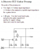
Related to AG's post #21:

So from that explanation can I liken the JFET's purpose in the guitar amp to be more like an effects pedal and not a preamp as I thought?

My efficiency question was in reference to using the resistor/diode vs. an IC. In the same vein - am I choosing one over the other based on my applications current needs and not worry about efficiency.

Now for updating,

I pieced it all together - 78l05 powering the BT dongle, 7809 powering the bridged lm386 amp w/o a JFET, and driving an 8Ω 25 watt RMS speaker.

I've used it a few nights at work and am happy to report it still has all it's magic smoke. It works well for what it is but I get some noise from the BT unit. From looking around I've found the problem is likely a ground loop an can be fixed by adding an isolation transformer. Would something like this DA103c work for me?

On another note I ordered some of the LM675 Staffan suggested and will try experimenting with some of those next. Should I start a new thread for those questions or just keep adding here?
 

Audioguru

Sep 24, 2016
3,656
Joined
Sep 24, 2016
Messages
3,656
Here is an electric guitar Jfet "preamp" and its explanations.
Here is a graph of the high frequency boost that a high impedance load has on a magnetic guitar pickup. Guitar speakers are usually just a simple woofer without a tweeter so the high frequency boost is important.
 

Attachments

  • guitar preamp.PNG
    guitar preamp.PNG
    15.4 KB · Views: 88
  • Guitar pickup peak.PNG
    Guitar pickup peak.PNG
    73.1 KB · Views: 39

Truckdrivingfool

Sep 30, 2012
33
Joined
Sep 30, 2012
Messages
33
So as the frequency increases it gives an extra push to drive the speaker better vs. as I thought it was needed for overall gain to drive the amp?
 

Audioguru

Sep 24, 2016
3,656
Joined
Sep 24, 2016
Messages
3,656
So as the frequency increases it gives an extra push to drive the speaker better vs. as I thought it was needed for overall gain to drive the amp?
The text on the schematic says that "the Jfet provides a very high impedance for the pickup" and "you do not need much gain" because a guitar magnetic pickup produces a high output level. Look in Google to read about "guitar magnetic Pickup resonance" (the high frequency boost).
 
Top