Maker Pro
Maker Pro

12vdc relay

mploeg

Jan 8, 2018
8
Joined
Jan 8, 2018
Messages
8
Hello all,

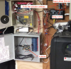
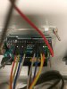
I'm trying to finish up a project left for our technology department. We have a project that requires 4 relays that are rated for 12vdc at 158 mA and my power supply is 12vdc at 2A. The wire used is copper 24 AWG and is 4 strands, but we only use 2 out of the 4.

The length of the wire (from power supply to relay) goes about 450-650 feet. I measured the voltage at each relay and the closet one gets about 12vdc while the furthest gets 10.6vdc.

Can anyone help? I'm not an electrician and this project was put in my lap. Should I look for a relay that requires less power (I tried calling and finding some) or should I just try and find a power supply that is a little larger? Any help is appreciated.

Thanks,
 

Kiwi

Jan 28, 2013
471
Joined
Jan 28, 2013
Messages
471
Parallel the two unused wires with the two being used. This will reduce the voltage drop in the wires to the relay.

Use a higher voltage power supply. 12v is the nominal voltage for the relays, but the specifications will probably give a maximum voltage of about 14v.
 

mploeg

Jan 8, 2018
8
Joined
Jan 8, 2018
Messages
8
Oh thank you very much, it might be a little before I can touch the project, but I will try this and tell you the results. I appreciate the input!
 

kellys_eye

Jun 25, 2010
6,514
Joined
Jun 25, 2010
Messages
6,514
Do you have any supply at the destination end (what's the relay powering?)

If there is one then use a transistor at the relay end to boost the current (signal in at the base via a resistor, relay in the collector circuit, ground the emitter).
 

mploeg

Jan 8, 2018
8
Joined
Jan 8, 2018
Messages
8
Hello Kellys_eye,

No power at the destination. The power source hits a central point and then branches to 3 relays (
Omron G7L-2A-BUBJ-CB DC12). Once the relay goes off it gives a signal to an arduino board to actuate. Would the method you suggested work in this situation?

Thanks,
 

AnalogKid

Jun 10, 2015
2,893
Joined
Jun 10, 2015
Messages
2,893
Do you need ground isolation between whatever is driving the relay coil and the arduino board connected to the relay contacts? If not, then the relay can be replaced with a 1-transistor circuit, or maybe just 2 resistors or 1 resistor and 1 zener diode. Driving the arduino input directly will take less than 1% of the relay coil energy, so voltage drops will not be a problem.

ak
 

KMoffett

Jan 21, 2009
723
Joined
Jan 21, 2009
Messages
723
Select a "12VDC" supply with +/- remote sense terminals. Two wires for power and two wires the detect the voltage at the relay end. The supply would need enough compliance to compensate for the voltage drop in the wires. Not a great solution, but It should work.

Ken
 

mploeg

Jan 8, 2018
8
Joined
Jan 8, 2018
Messages
8
Do you need ground isolation between whatever is driving the relay coil and the arduino board connected to the relay contacts? If not, then the relay can be replaced with a 1-transistor circuit, or maybe just 2 resistors or 1 resistor and 1 zener diode. Driving the arduino input directly will take less than 1% of the relay coil energy, so voltage drops will not be a problem.

ak

Hello Analogkid!

Thank you for your input. Kind of speaking a little foreign to me so I'll do some research on your suggestion. I'll upload a picture of one of the relay's arduino board combos. The way we want it to function is for a switch to go off, send power over 24AWG pair (I'm going to try and put 2 and 2 strands together now) and then hit the 3 relays (each about 450ft-600ft away from central split and then once the relay goes off it lets the arduino board know that it can activate.

Please let me know if that helps?

Also I know this is very bad wiring, but it's the example of the smaller working system we have. Cleanup is in the future. :D
 

Attachments

  • Screen Shot 2018-01-08 at 5.18.21 PM.png
    Screen Shot 2018-01-08 at 5.18.21 PM.png
    718.7 KB · Views: 134

KMoffett

Jan 21, 2009
723
Joined
Jan 21, 2009
Messages
723
I'm confused. Is the photo of the sending or the receiving (4 relays) end?. Can you sketch a block diagram showing what is where.

Ken
 

kellys_eye

Jun 25, 2010
6,514
Joined
Jun 25, 2010
Messages
6,514
Doesn't that mean there is power to the Arduino board? Are the Arduino/relay adjacent to each other?

A block/wiring diagram would be useful.
 

Robert_fay

Jun 15, 2017
124
Joined
Jun 15, 2017
Messages
124
My question would be if the relay is working or not. Looking at the specs it appears you are using a relay such as Z1051-ND from Digi-Key Omron part G7L-1A-BUB-J-CB-DC12 and that relay has a Turn on Max of 9VDC meaning any voltage over 9V will turn on the relay so 10.6 though not ideal should have no issues turning on the relay. here is the diagram. Remember since this is a relay 10.6v on the control side is not an indication of voltage on the circuit side. The fact that it is actuating the Arduino seems to indicate the relay is working.

upload_2018-1-9_10-7-45.png
 

mploeg

Jan 8, 2018
8
Joined
Jan 8, 2018
Messages
8
I'm confused. Is the photo of the sending or the receiving (4 relays) end?. Can you sketch a block diagram showing what is where.

Ken

Apologies for the late response I've been working on a couple of different things. I hope this helps? I'm starting in the office with one 12vdc power supply and just trying to actuate the relays. Please see attached.
 

Attachments

  • Relay Project.pdf
    196.9 KB · Views: 38

mploeg

Jan 8, 2018
8
Joined
Jan 8, 2018
Messages
8
Doesn't that mean there is power to the Arduino board? Are the Arduino/relay adjacent to each other?

A block/wiring diagram would be useful.

Hello Kellys_eye,

Apologies for the late response. Arduino boards have their own power supply. I hope this helps? I'm starting in the office with one 12vdc power supply and just trying to actuate the relays. Please see attached. All I need is for the relay to actuate and the rest is automated.
 

Attachments

  • Relay Project.pdf
    196.9 KB · Views: 49

mploeg

Jan 8, 2018
8
Joined
Jan 8, 2018
Messages
8
My question would be if the relay is working or not. Looking at the specs it appears you are using a relay such as Z1051-ND from Digi-Key Omron part G7L-1A-BUB-J-CB-DC12 and that relay has a Turn on Max of 9VDC meaning any voltage over 9V will turn on the relay so 10.6 though not ideal should have no issues turning on the relay. here is the diagram. Remember since this is a relay 10.6v on the control side is not an indication of voltage on the circuit side. The fact that it is actuating the Arduino seems to indicate the relay is working.

View attachment 38415

Hello Robert_fay,

Thank you for the input. I did not know about the difference in the coil. I'm going to try a couple of different things tomorrow afternoon with power supplies and relays. I'm wondering if a 24vdc supply would burn it out after a while?
 

Robert_fay

Jun 15, 2017
124
Joined
Jun 15, 2017
Messages
124
I'm wondering if a 24vdc supply would burn it out after a while?

If it is indeed the G7L-1A-BUB-J-CB-DC12 the max coil voltage is 110% so you would not want to run 24V.

In the pic you say "0V but activates arduino". Does that not tell you it is working?
 

mploeg

Jan 8, 2018
8
Joined
Jan 8, 2018
Messages
8
If it is indeed the G7L-1A-BUB-J-CB-DC12 the max coil voltage is 110% so you would not want to run 24V.

In the pic you say "0V but activates arduino". Does that not tell you it is working?

I'll have to re-measure I didn't get a reading when it functioned and I can complete the circuit with the test button and no power being sent to the relay by pressing it so I would assume that it isn't actuating the arduino. The board has two pins that go to the relay. The ground and RX. If I touch those two cables together the whole system actuates as well. Please see attached for the two pins on board that go to the relay.
 

Attachments

  • PES S_F1.JPG
    PES S_F1.JPG
    200.2 KB · Views: 71

KMoffett

Jan 21, 2009
723
Joined
Jan 21, 2009
Messages
723
Trying to make this a more conventional schematic designations
Lower right: office
Lower center A
Lower left: B
Middle center: C
Upper right: D
A is only a source for 12VDC?
Where is Arduino? B?
What voltage and current are relays contacts B,C, and D switching. Looking for smaller relays.

Ken
 

Robert_fay

Jun 15, 2017
124
Joined
Jun 15, 2017
Messages
124
I am showing this as your relay circuit.
upload_2018-1-11_16-44-25.png
I would verify this is how you have it wired.upload_2018-1-11_16-41-37.png
2&4 can be switched and 0&1 can be as well.
 
Top