So I have a circuit that I wrote up on my lunch break for a project in which I am taking an old 1981 model IBM 5150 and installing modern guts, and I want it to look all original on the outside and to use the original power switch on the back right side to turn on a new motherboard.
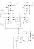
The circuit I drew up gives the PWR SW on a new mATX motherboard a 1 second connection via a relay for both the ON and OFF power switch position by use of 4 relays. 2 of the relays are for the ON and OFF state and flip-flop depending on switch position to charge 2 capacitors in alternation. When Relay 1 or 2 is deenergized the capacitor is then brought to the 3rd or 4th relays depending on which state the power switch is switched to ON or OFF. This capacitor causes the relay #3 or #4 to energize for about 1 second. ( Relay# 1 is the primary for relay #3, and relay #2 is the primary for relay #4, and Relay 1 and 2 flip flop between energized and deenergized depending on the power switch position, and relays #3 and #4 supply the 1 second connection to motherboards PWR SW pins when energized to simulate a user pushing the power button of a new computer for 1 second ).
So the question I have is that I am using the 1N4148 diodes on Relay #1 and Relay #2 to protect my contacts from the high voltage spike of the coil EMF collapse. But on Relay #3 and Relay #4 I would like to just keep the electrolytic capacitors there without the 1N4148 diodes because they seem not necessary. Are they unnecessary as I believe they are when the electrolytic capacitor when brough across the coil will just drain to 0 volts?
The contact to the coil will only open when the capacitor is to be charged in which there is no potential because it has been drained out.
I generally put diodes across all relay coils to protect contacts as well as blowing out the relay drivers from spikes, but back in college the teacher pounded it in as a rule for all relays to have this diode across the coil, which I dont believe pertains to the use that I have intended for relay 3 and 4.
Last edited: