Maker Pro
Maker Pro

Yagi-Uda antenna 2100MHz

flippineck

Sep 8, 2013
358
Joined
Sep 8, 2013
Messages
358
Here is my local (UK) cell tower:

Station Type: Macrocell
Height of Antenna: 13.7 Metres
Frequency Range: 2100 MHz
Transmitter Power: 17.89 dBW
Maximum licensed power: 35 dBW
Type of Transmission: UMTS

It's no more than a mile away. There are no very major obstructions to line of sight but, there is some moderately raised ground, trees, a few houses etc. between the mast and my roof.

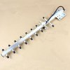
I'm using a 10 element Yagi-Uda antenna (8 directors, one driven element, one reflector) designed for 2100MHz connected to my 3G router via less than 1 metre of RG58 coax & some SMA connectors.

Having trouble getting a good signal especially when the weather's wet. I've tried repositioning the antenna including outdoors, remaking the connections, shortening the coax as much as possible.

I did notice something that strikes me as odd about the (Chinese-made) antenna. The boom of the antenna is made of square section aluminium hollow bar. The directors and the reflector are all made of aluminium tube. They all fit into holes drilled in the boom, and are then held in place by 'crimps' made in the side of the boom.

This would mean that electrically, every director and the reflector, are all shorted together at their midpoints by the boom.

I tend to think in DC and very low frequency AC terms, high frequencies get too esoteric and mathematical for me.. so maybe this design is perfectly ok given the whole thing is designed to do what it does at 2100MHz.

Maybe it's just a load of rubbish simply designed to 'look the part' though?

Need to pick the brains of someone who's into radio stuff here I think?

Attached: representative image - not my antenna but one very similar
 

Attachments

  • yag.jpg
    yag.jpg
    10.6 KB · Views: 1,196
Last edited:

davenn

Moderator
Sep 5, 2009
14,264
Joined
Sep 5, 2009
Messages
14,264
It's no more than a mile away. There are no very major obstructions to line of sight but, there is some moderately raised ground, trees, a few houses etc. between the mast and my roof.

I'm suprised you would even need an external ( outside ) antenna. Does your router have its own whip antenna ?

This would mean that electrically, every director and the reflector, are all shorted together at their midpoints by the boom

that's totally normal for a yagi

Maybe it's just a load of rubbish simply designed to 'look the part' though?

that's quite possible .... looking good doesnt imply works well. A couple of mates spent good money on a couple of 18 element 1296MHz yagis. My homebrew 9 ele yagi blew them out of the water ... unbelievable that commercially designed yagis were such crap!!

Cheers
Dave
 

duke37

Jan 9, 2011
5,364
Joined
Jan 9, 2011
Messages
5,364
Several years ago, a friend lost his ITV TV signal during the summer but the BBC was unaffected. The ash tree at the end of his garden had leaves that were resonant at the TV frequency. Chose a tree with different sized leaves or install a 100ft mast !
 

Arouse1973

Adam
Dec 18, 2013
5,178
Joined
Dec 18, 2013
Messages
5,178
Too strong a signal can cause issues, might need an atenuator,just a thought.
Adam
 

flippineck

Sep 8, 2013
358
Joined
Sep 8, 2013
Messages
358
Thanks guys that's really helpful.

The router works okay by itself, generally comes up with "1 bar out of 5" and I get up to about 10 Meg d/l speeds on the ookla speedtest.

Odd thing is, plugging in the yagi seems to add nothing to either the signal "bars" nor the connection speed / reliability.

This is with my new huawei router like this one www.ebay.com/itm/181275789569

I used to use an old huawei E160 USB dongle to get on the net, the yagi often took that from 1 bar up to 5 bars.

The wet weather seems to have a massively deleterious effect on the connection. Have to see if things improve in the dry. It's raining heavily all the time at the mo here.
 

(*steve*)

¡sǝpodᴉʇuɐ ǝɥʇ ɹɐǝɥd
Moderator
Jan 21, 2010
25,510
Joined
Jan 21, 2010
Messages
25,510
The ash tree at the end of his garden had leaves that were resonant at the TV frequency.

I can just imagine the BBC sponsoring the planting of thousands of Ash trees...
 

flippineck

Sep 8, 2013
358
Joined
Sep 8, 2013
Messages
358
Just spent some time stripping down the connection box on the antenna.

On a normal Yagi, the driven element is a straight, centre-fed dipole yes?

This antenna isn't like that. The driven element seems to be a strip of aluminium maybe 6mm wide by about 13cm long (wild guess on the length there) which is formed into a broadly rectangular-with-rounded-ends hoop. The 'hoop' is placed in line with the directors and reflector. One end of the hoop is connected to the RG58 coax's centre conductor, and the other end is connected to the coax's shield.

There is a weird thing which seems to be soldered across the ends of the hoop too - a roughly two inch length of what appears to be a very, very fine type of coax - diameter about one millimetre.

This very fine coax seems to be connected across the main feed coax, braid to braid and centre conductor to centre conductor.

Is this some sort of impedance - controlling arrangement?

With the coax disconnected from the ally hoop, but the fine coax still soldered to the main coax, there is no DC continuity between the feedline's braid and centre.

What I did notice was that before disassembly of the innards of the connection box, there was a lot of corrosion and there seemed to be no continuity between the hoop and either the braid or centre of the feed coax.

I unscrewed everything and did the old vinegar and salt and coke routine to clean up all the corrosion, then when everything was bright and clean and dry again, screwed it all back together just as it was before - now I'm getting direct DC continuity across the feedline and onto the ally hoop element.

rigged up everything onto the router again and.... same as before, v poor signal.

I'm going to try building a mad 19 element dipole yagi out of brakepipe and sticks now :D
 

(*steve*)

¡sǝpodᴉʇuɐ ǝɥʇ ɹɐǝɥd
Moderator
Jan 21, 2010
25,510
Joined
Jan 21, 2010
Messages
25,510
You're correct. The small coax may there to both match impedance and/or to convert from an unbalanced to a balanced line.

Some antennas are open circuit at DC, others are short circuit. At the operating frequency they will have the same impedance though -- or should do.

I have two antennas on my roof for 2.4GHz use. One is a dead short, the other is open. It helps me figure out which coax is which :)
 

davenn

Moderator
Sep 5, 2009
14,264
Joined
Sep 5, 2009
Messages
14,264
Antennas are weird and wonderful things and it takes a while of working with them to get ya head around the way they work

as steve said ....
Some antennas are open circuit at DC, others are short circuit. At the operating frequency they will have the same impedance though -- or should do.

when it comes to DC readings that is using the ohms range on a multimeter, you can usually ignore the reading UNLESS you KNOW what sort of reading to expect

this 2.4GHz antenna feed below RESISTANCE will read a short circuit on Ohms and for a DC voltage across it. But its AC IMPEDANCE at 2.4 GHz will be 50 Ohms.

attachment.php


The rectangular copper band is the driven element, there's a director to the left and a reflector to the right. This is a close up of the feedpoint of my 16 element yagi. The directors and reflector and part of the mounting is stamped out of a chun k of sheet aluminium.
the looped driven element if out on its own would have a feed point impedance of 300 Ohms, this is typical for what we call a folded dipole. But once it is incorporated into a yagi arangement, the resulting interactions with the other elements drops the feedpoint impedance considerably

You may notice there is a lump in the coax feed between the connector and the feedpoint. There are several ferrite beads held in place by some heatshrink tubing. These ferrite beads have 2 purposes
1) they form a RF choke that stops RF currents from travelling back down the shield (braid) of the coax and be radiated. That is BAD

2) they form a BALUN the folded dipole is a BALanced point in the transmission system. Coax cable is UNbalanced.

So a BALUN is a balanced to unbalanced transformer

OK in next post will look at a ygi feed that will test open circuit at DC

cheers
Dave
 

Attachments

  • 2400MHz_Yagi_Feed.jpg
    2400MHz_Yagi_Feed.jpg
    61.3 KB · Views: 6,378
Last edited:

davenn

Moderator
Sep 5, 2009
14,264
Joined
Sep 5, 2009
Messages
14,264
OK in this yagi I have for 1296MHz ( 1.29GHz) the driven element is just a straight rod

attachment.php


Again in this image you are just seeing part of a larger yagi, a 9 element one. You can see that the dipole driven element, DE, is just a straight piece of brazing rod throguh the wooden boom as are the reflector, REF and first director, DIR1
running along the top of the wooden boom is a copper tuble with the inner conductor and dielectric inside it. In this yagi, that is the BALUN, the centre conductor connects to the short length of copper tube going to the right. Inside that small tube is a smaller inner inner conductor and teflon dielectric ( you can see it poking out at the right end and connected to the dipole DE with a short strip of metal.
This type of feed matching is called a Gamma Match that small short tube, the teflon dielectric and inner conductor form a capacitor. And because there is a capacitor in the centre conductor path to the driven element the DC resistance reading will show an open circuit

attachment.php


cheers
Dave
 

Attachments

  • IMGP6614a.jpg
    IMGP6614a.jpg
    114.4 KB · Views: 3,697
  • gamma match.GIF
    gamma match.GIF
    2.1 KB · Views: 3,459
Last edited:

davenn

Moderator
Sep 5, 2009
14,264
Joined
Sep 5, 2009
Messages
14,264
ohhhh just to expand on this comment from you

This would mean that electrically, every director and the reflector, are all shorted together at their midpoints by the boom

you can see that those 2 yagis I have shown are different. The first one has elements connected to metal boom at their centre point, the second one uses a woodem boom so there is no common point of contact. It really all boils down to how you want to design your yagi, neither one is any better than the other RF performance wise.

the only real advantage is a mechanical sturdiness one where the elements are solidly connected to the boom or as in my 2400 MHz yagi, an intergral part of the metalwork.

as far as construction goes, considerations are taken into account for element length when elements are connected to a metal boom. At freq's up to a few 100 MHz its not really a problem but at UHF and SHF freq's it becomes a real consideration

cheers
Dave
 

flippineck

Sep 8, 2013
358
Joined
Sep 8, 2013
Messages
358
Thanks :)

The side wall of my house is about 10 - 15 degrees off a straight line to the transmitter.

This means, if I have the yagi placed as high as possible inside the house (office in the box room on the top floor), I'm aiming it at the tower at an acute angle to the wall (see image)

What sort of signal attenuation would this be likely to produce relative to the antenna being substantially at the same height, but on a bracket on the outside of the wall. coax length would be the same one metre or so as it is now.
 

Attachments

  • yagiplacement.jpg
    yagiplacement.jpg
    11.8 KB · Views: 511

duke37

Jan 9, 2011
5,364
Joined
Jan 9, 2011
Messages
5,364
The wall will produce a large attenuation at these frequencies, particularly if wet. Put the aerial outside and away from the wall. An extra meter or so of co-ax should not cause too much attenuation.
 

flippineck

Sep 8, 2013
358
Joined
Sep 8, 2013
Messages
358
Just tried drilling a hole in the wall & dangling a length of RG58 through it, with 35mm of inner exposed and 35mm of braid turned back against the cable to form a vague attempt at a sort of upside down, blow in the wind 1/4 wave dipole. (darness fell & don't fancy going up the ladder to bolt up the yagi)

Used an online calculator to arrive at the 35mm length for 2100MHz

Router was able to 'see' the yagi before, and automatically configure itself to use 'external antenna' rather than 'built-in'.

This time, router could not see the external antenna and had to be manually configured.

Wonder if the router tries to detect an external antenna by measuring DC resistance across the SMA antenna port? My stripped RG58 dipole would show open circuit where the yagi showed a short?

Still only 1 bar out of 5. But, when the external antenna was manually switched in, ping times fell markedly, download and upload speeds increased a little, and browsing became just about useable.

I made no attempt at a balun or anything like that, I just stripped back 35mm of braid and folded it back and taped it up. so I could pass the whole thing through the drilled hole and let it hang outside. Not like a 'T' shape like a proper dipole.
 

davenn

Moderator
Sep 5, 2009
14,264
Joined
Sep 5, 2009
Messages
14,264
I made no attempt at a balun or anything like that, I just stripped back 35mm of braid and folded it back and taped it up.

If I understand correctly what you did then you have just made a 1/4 wave whip out of the end of the coax. you should have it pointing up tho probably work a little better as it would get the polarisation correct

attachment.php


yes it will work, but its gain compared to the yagi will be very low.
Around 1 to 2 dBd compared to the yagi which should ( if it's working properly) at least 10 dBd

cheers
Dave
 

Attachments

  • 2100MHz whip.GIF
    2100MHz whip.GIF
    3 KB · Views: 2,979

flippineck

Sep 8, 2013
358
Joined
Sep 8, 2013
Messages
358
Done as you suggested.

Still only "one bar out of 5" but ping times have gone down a bit more & speeds risen a bit more, so either the network is less congested or the whip antenna is working a little better?

47ms ping and around 7 meg download speed, that's perfectly useable
 

(*steve*)

¡sǝpodᴉʇuɐ ǝɥʇ ɹɐǝɥd
Moderator
Jan 21, 2010
25,510
Joined
Jan 21, 2010
Messages
25,510
I'd probably point it down to keep water out of the coax.

You could look up bi-quad antennas. They're easy to make and provide pretty good gain.
 

flippineck

Sep 8, 2013
358
Joined
Sep 8, 2013
Messages
358
Have now bolted up the yagi properly. Very little improvement, still only 1 bar :( well, it's useable but I was hoping for better.

Perhaps I need a signal amplifier or something?

Will have a look at bi-quads.

I figure this antenna must transmit as well as receive, so thinking back to my 27MHz (?) CB days back in the 80's, do I need to be thinking about SWR? I had a quick look on ebay and I can't really see any SWR meters for 2100MHz.

There are loads of signal strength meters on ebay for around the 800MHz area, stuff for satellite TV, DVB etc.. can you easily get signal strength meters with SMA connectors for 2100MHz?

I'm wondering if, the tower I *think* is my closest, even has a working transmitter on it for my network.. maybe I need to aim somewhere else (although I've already tried rotating the yagi & I haven't seen any major difference in any particular direction)
 

Attachments

  • yagi.jpg
    yagi.jpg
    37.8 KB · Views: 560
Last edited:

(*steve*)

¡sǝpodᴉʇuɐ ǝɥʇ ɹɐǝɥd
Moderator
Jan 21, 2010
25,510
Joined
Jan 21, 2010
Messages
25,510
What sort of coax are you using? If it's not coax designed for this frequency it may simply be attenuating the signal to nothing.

If I recall correctly, RG58 at these sort of frequencies loses about 3db per metre. (At 1GHz, you're looking at 21db/100ft. And it rises rapidy...)

I think LMR-400 is what I used for short runs, and a larger solid coax for longer runs.
 

flippineck

Sep 8, 2013
358
Joined
Sep 8, 2013
Messages
358
Well I'm only *assuming* that it's RG58. It seems to fit the descriptions I've read online for RG58, it fits the RG58 SMA connectors I've bought nicely, and it came as a 10 Metre length attached to the 2100MHz yagi.

There's nothing printed on the cable itself though, it's just plain black.

I could try getting different cable I guess

edit.. omg 2 bars just before bed. woohoo i'm well happy, all that effort not entirely wasted then
 
Last edited:
Top