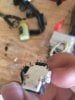
Kind of a poor pic...
The joysticks used in the Xbox, Xbox-S, and Xbox 360 controllers as far as I know are all simple just a pair of potentiometers. The joystick there looks the same.
Notice the 2 groups of 3 pins?
One group of 3 will be for the X axis, the other for the Y axis.
There may be an additional pair of wires for the embedded push-button for when the joystick is depressed...
In any case... The group of 3 wires are usually power, signal, ground. Signal is an analogue voltage between power and 0V (ground) and is fed into a DAC.
You could also measure the resistance from the middle pin to either one of the other two. As you move the stick, the resistance will vary.
You can, of course measure yourself... measure resistance with the groups of 3 to determine which one is responsible for each axis. The pin that changes as the stick moves is signal. The other two pins are power and ground... and can be swapped to 'invert' the direction the joystick is interpreted as.
The pair of pins responsible for the depressing the stick can be found the same way... measure, test, observe. Repeat until all the pins are labelled.