Hello, I am hoping someone can assist me in determine the correct way to wire a project that I am currently working on. I have totally confused myself on how to wire each control.
My Goal:
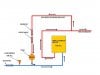
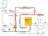
To install a flow switch/sensor into the main hot water line coming from the heater, this will turn on when it senses the draw for hot water. - Then the output from the sensor will activate the 10sec “delay-on” relay. Once the ten seconds has elapsed the relay will turn the pump that circulates the water throughout the system. – Once the draw for the main flow of hot water is stopped, the flow sensor will not recognize this because the pump will generate the flow over the sensor and therefore the pump will continue to run (this is ok). – On the hot water return pipe that the water continues to flow through there is an aquastat which is set to 130 degrees, once the aquastat senses that the water has reached 130 degrees it will break the current to the pump and therefore there will won’t be any flow of water over the flow sensor. Then the system will reset itself till the next time there is a demand for hot water. In theory this should work.
SEE Attachments
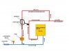
• System Design
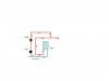
• My Best Guess on Wiring this Project
Parts list: WILL FOLLOW IN NEXT POST
Since I have 110v ac at the location I plan on operating all controls by 110v ac. Due to the large number of wires and connection I have managed to completely confuse myself and would hate to damage any of these devices. Therefore any help would be greatly appreciated.
I should mention that all of the items are installed in the system and that the aquastat has been installed and set to cut out at 130 degrees. The problem I am having is how the flow meter and relay should be energized also where the pump leads and aquastat should be tied into the circuit. I have tried to map the connections out on paper but I get confused with the purpose of each wire on the relay and flow meter.
My Goal:
To install a flow switch/sensor into the main hot water line coming from the heater, this will turn on when it senses the draw for hot water. - Then the output from the sensor will activate the 10sec “delay-on” relay. Once the ten seconds has elapsed the relay will turn the pump that circulates the water throughout the system. – Once the draw for the main flow of hot water is stopped, the flow sensor will not recognize this because the pump will generate the flow over the sensor and therefore the pump will continue to run (this is ok). – On the hot water return pipe that the water continues to flow through there is an aquastat which is set to 130 degrees, once the aquastat senses that the water has reached 130 degrees it will break the current to the pump and therefore there will won’t be any flow of water over the flow sensor. Then the system will reset itself till the next time there is a demand for hot water. In theory this should work.
SEE Attachments
• System Design
• My Best Guess on Wiring this Project
Parts list: WILL FOLLOW IN NEXT POST
Since I have 110v ac at the location I plan on operating all controls by 110v ac. Due to the large number of wires and connection I have managed to completely confuse myself and would hate to damage any of these devices. Therefore any help would be greatly appreciated.
I should mention that all of the items are installed in the system and that the aquastat has been installed and set to cut out at 130 degrees. The problem I am having is how the flow meter and relay should be energized also where the pump leads and aquastat should be tied into the circuit. I have tried to map the connections out on paper but I get confused with the purpose of each wire on the relay and flow meter.