Maker Pro
Maker Pro

Will this circuit work for my LEDs (555 timer/3w leds)

TheSinpy

Feb 9, 2014
20
Joined
Feb 9, 2014
Messages
20
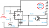
I’ve asked a Similar question about month ago about making a circuit to flash/power some 1watt leds I got off eBay. https://www.electronicspoint.com/circuit-support-my-needs-1w-led-x3-flasher-t267233.html

The circuit is shown at bottom of my post. I wanted to know will same thing work for my new project or is there something else I should do?

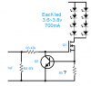
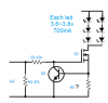
The specifications for the new leds are 2.2v~2.8v 700mA.
Another question should I make my power supply a 6volt battery like this? http://img.rakuten.com/PIC/47673486/0/1/1000/47673486.jpg
This light is intended to be used on a bicycle for a tail light. Hoping for a run time of hour to two hours.


--------------
Credit:
https://www.electronicspoint.com/got-question-driving-leds-t256849.html
 

Attachments

  • 3x1w leds 555 timer.png
    3x1w leds 555 timer.png
    17.5 KB · Views: 2,023

Harald Kapp

Moderator
Moderator
Nov 17, 2011
13,719
Joined
Nov 17, 2011
Messages
13,719
Looks fine to me. Go ahead.
You may want to add a 100µF electrolytic capacitor across the power supply input pins for better stability, but that is not absolutely necessary.
 

(*steve*)

¡sǝpodᴉʇuɐ ǝɥʇ ɹɐǝɥd
Moderator
Jan 21, 2010
25,510
Joined
Jan 21, 2010
Messages
25,510
I've just gone back to check that thread (thanks for the link and the attached schematic) and I think this should be fine for 2 LEDs at 700mA. A 1 ohm resistor will give you something like 600mA. A 1 ohm in parallel with a 12 ohm resistor will give you something much closer.

The mosfet you have should be capable of the extra power.

Note that all excess voltage is dropped across the mosfet, so if you're also running this from 14V, the mosfet will have up to 9V across it at 700mA, and will dissipate 6.3W. This will make it get too hot unless it has a heatsink.
 

TheSinpy

Feb 9, 2014
20
Joined
Feb 9, 2014
Messages
20
I'd be running it off 6 volt battery or a 12volt. The 14volt power supply was from my last circuit I was trying to make.

Im still bit lost in the mist when it comes to picking transistors and mosfets. I only have one more left that I got from the Digkey Web site. http://www.digikey.com/product-search/en?vendor=0&keywords=fqpf13n06l
The cost of shipping online I like to switch to something else. I've found this one at my Radio Shack. The spects looks like it would work. Could it replace the one I've listed above? http://www.radioshack.com/product/index.jsp?productId=2062618
 
Last edited:

(*steve*)

¡sǝpodᴉʇuɐ ǝɥʇ ɹɐǝɥd
Moderator
Jan 21, 2010
25,510
Joined
Jan 21, 2010
Messages
25,510
It's bizzare that Radio Shack show the device upsidedown and their "tech" specs don't even link to a datasheet.

But yeah, that one should be fine.

I'd run the circuit from 6V if possible.
 

TheSinpy

Feb 9, 2014
20
Joined
Feb 9, 2014
Messages
20
The circuit worked but looking at the schematics it shows the positive of the LEDs going to the positive supply, and the negative going to the D (Drain) Of the mosfet. When powering my leds it only works with the positive going to the D (Drain) of the mosfet and the negative (LED) going to the negative power supply?


---------------------
Screen shots don't have anything do with the question above
 

Attachments

  • LED 1.jpg
    LED 1.jpg
    21.9 KB · Views: 249
  • LED 2.jpg
    LED 2.jpg
    22.4 KB · Views: 331

jpanhalt

Nov 12, 2013
426
Joined
Nov 12, 2013
Messages
426
Are your sure the LED's leads are properly identified? This is the standard way:
upload_2014-4-9_18-9-11.png

But, it is possible some villain has snipped the anode lead to be shorter. Test the Led's with a battery and resistor in series to be sure the leads are correctly identified.

John
 

TheSinpy

Feb 9, 2014
20
Joined
Feb 9, 2014
Messages
20
Its one of them bead leds far as I know it doesn't have any markings on it. I've got the wires hooked to them right on to a star heat sink. I'm not going question to much because its working. I just wondering why it only worked the way it did, and not as its shown on the schematics with the positive of the LEDs going to the positive power supply and negative going to the D of the mosfet

---------------------------------------
http://image.dhgate.com/albu_277624365_00-1.0x0/led-beads-high-power-3w-led-lamp-180-200.jpg
 

TheSinpy

Feb 9, 2014
20
Joined
Feb 9, 2014
Messages
20
I've got one last question, The values for Q2 doesn't really matter other than it can handle the voltage I'm putting though it right?
 

Attachments

  • 3x1w leds 555 timer.png
    3x1w leds 555 timer.png
    17.5 KB · Views: 352

(*steve*)

¡sǝpodᴉʇuɐ ǝɥʇ ɹɐǝɥd
Moderator
Jan 21, 2010
25,510
Joined
Jan 21, 2010
Messages
25,510
Yeah, Q2 is just a garden variety small signal NPN transistor. Pick your favorite.

If you don't have one may I suggest your new favorite could be a BC548, or a 2N2222 (if you're an American).
 

neon

Oct 21, 2006
1,325
Joined
Oct 21, 2006
Messages
1,325
For a 555 [ good for 200 ma ] timer driving 3 IEDS it is not necessary to add drivers normally LED works on 10 ma forward current. . you may increase the current to the maximum of the device temperature operation. I suggest if anything add a transistor current source to limit the current or add a proper resistor to limit the current for the LEDS to a proper value Not all LEDS are created the same reds doing fine with 1.8v forward blues may need 3.4v and above. That is why a current source is a better and safer design. I WOULD either add the current source or split the LEDS and add the limiting resistor No external drivers are necessary
 

(*steve*)

¡sǝpodᴉʇuɐ ǝɥʇ ɹɐǝɥd
Moderator
Jan 21, 2010
25,510
Joined
Jan 21, 2010
Messages
25,510

dh390

Jul 30, 2013
33
Joined
Jul 30, 2013
Messages
33
TheSnipy might I add some possible additions to your project. I don't know what type of battery system you are thinking of using but I have some posbilities.

A setup using highe capacity Ni-MH batteries like 4 10000mAh C cells that can be gotten off E-Bay. Your 6v

Or 4 Ni-MH 3500mAh + AA batteries and add a tire driven generator.

The generator could be used to power the LED circuit and recharge the batteries. The batteries (or even a Super Capacitor) would be used to power the LED circuit when you have to stop or pause in your bike ride like at a stop sign.

You could use a small DC motor like those used in remote controled cars or those powered kids cars (9 to 18v) for a generator and a simple regulator to prevent over voltage due to speed.

Just a thought.
 

TheSinpy

Feb 9, 2014
20
Joined
Feb 9, 2014
Messages
20
Thanks dh390, I was thinking about a 6 volt Sealed lead acid battery. Found one for about $10 at a store, just not sure how long the lights would be powered for till it goes dead. It would be nice ideal to have a small generator to recharge the batteries, but last thing I rigged on my bike fell off and messed up my rear derailleur :\ I don't know much about the Super Capacitors but they look like a fun thing to play around with but where would I even get them?

I got one more question. This circuit I made is making the leds run at full power or only half power? Seems like there a difference in brightness when I hook the leds to a battery with a resistor and powering it though the circuit.
 

Attachments

  • led.png
    led.png
    616 KB · Views: 315
Last edited:

(*steve*)

¡sǝpodᴉʇuɐ ǝɥʇ ɹɐǝɥd
Moderator
Jan 21, 2010
25,510
Joined
Jan 21, 2010
Messages
25,510
What value resistor are you using?

The best thing to do is to measure the voltage across whatever you're using and use ohms law to determine the current.

You do it this way because it cancels out all other influences other than the tolerance of the resistor. If you want to cancel most of that out you can accurately measure the actual resistance of the resistor.
 

TheSinpy

Feb 9, 2014
20
Joined
Feb 9, 2014
Messages
20
was 5volt about 3.5ohms. Im not to worried about this maybe it just flash rates that make the brightness deterrent.
 

TheSinpy

Feb 9, 2014
20
Joined
Feb 9, 2014
Messages
20
What is the max voltage or current this thing can handle?

Changing the question from two red leds to something else
Would leds in 8 leds be to much for this thing to power?
Two sets of 4x leds in series/parallel with each other
 

Attachments

  • leds.png
    leds.png
    14.1 KB · Views: 233

TheSinpy

Feb 9, 2014
20
Joined
Feb 9, 2014
Messages
20
I don't know why I can't edit or delete my last post but thinking about it, Two sets of 3x leds in series/parallel with each other. Not 4x leds
 

Attachments

  • leds.png
    leds.png
    13.1 KB · Views: 232

(*steve*)

¡sǝpodᴉʇuɐ ǝɥʇ ɹɐǝɥd
Moderator
Jan 21, 2010
25,510
Joined
Jan 21, 2010
Messages
25,510
Placing LEDs in parallel (or strings of LEDs in parallel) is not advisable. This is especially true where the LEDs operate at high power as yours do.

It is best to have one current regulator for each string. In this case, everything except for R4 needs to be replicated.

The value of R5 is about 0.6/I where I is the desired current So for 700mA, you want about 0.86 ohms. I'd start with a 1 ohm resistor and see how it goes.
 
Top