Maker Pro
Maker Pro

Wi Lite wireless lighting switch

bushtech

Sep 13, 2016
1,025
Joined
Sep 13, 2016
Messages
1,025
Sir 73's de Edd

You are a marvel Sir. Thank you.

I think it will be a lot easier to figure out this diode with a photo which shows this diode as one of a set of 4. You can see them there where it shows D4 and D8

20160923_084535.jpg
 

Attachments

  • 20160920_201120.jpg
    20160920_201120.jpg
    242.2 KB · Views: 155

bushtech

Sep 13, 2016
1,025
Joined
Sep 13, 2016
Messages
1,025
If it will help this board blew the blue mov and the resistor next to it which I replaced but the board was still dead.
 

73's de Edd

Aug 21, 2015
3,622
Joined
Aug 21, 2015
Messages
3,622
Unfortunately I work best seeing the other side of the board . . . .

But an initial rough analysis seems to be finding AC line input coming in thru the BLUE input surge varistor and then into the 100 ohm film resistor and then into the Gee-iant GREEN polyester film capacitor . To be utilizing the units capacitance reactance for line voltage dropping purposes.
Will peeling off the top black covering reveal that capacitors voltage and capacitance rating ?
Unless that info is on one of its sides.
Now we seem to be shooting for a max 24VDC voltage for the power relay and a sub voltage for the corner RF WI FI module.
I see one MELF damping diode for the POWER relay coil, being near it.
BUT the 4 diodes that surround the main electrolytic may be ordinary diodes, just being supplied by GENERAL . . . since they were BIG on diodes.
That's where the foil path profile on the other side of the board comes into play for "reading" its adjunct circuitry.

BTW do you know the branding of that WI-FI switch board ?

Thasssit . . .for now . . . .

73's de Edd
 
Last edited by a moderator:

bushtech

Sep 13, 2016
1,025
Joined
Sep 13, 2016
Messages
1,025
Thanks St Edd.
Markings on beeeg cap: IEC/UL 60384-14
F862 X2 310-
SF5 40/110/56B
Markings on board: 94V-0 928DS (could be 328)
E193317

You can see the logo on the board just next to the white sticker which I had to pull off to get to the markings on board above.

Here is the other side of the board. This is the actual one that blew, I have 2 of these switches so some photos are of the undamaged switch

20160927_143147.jpg

Please constructive criticism only on my soldering. I know it sucks but I'm trying my best:eek:

And here's a photo of the beeeeeg cap showing logos:

20160927_143429.jpg
Please note that this board pushes out 220v to the lights
 

73's de Edd

Aug 21, 2015
3,622
Joined
Aug 21, 2015
Messages
3,622
Sir Bushtech. . . . . . .

Will add on more info later but, for now, can you give the cap values and voltages of the 3 electrolytic caps BLUE, ORANGE and CHARTREUSE

And see if those 4 diodes aren't just being conventional diodes ( measure Vf's )and are the parts of a FWB feeding into the BLUE elect cap . . .which then feeds power to the 24V relays coil and then further divides down for reduced supply voltages at OR and CHART capacitors, which then feed the RF module . . . . . also find the small flat pack . . . U2's . . . part number .

PIC REFERENCE . . . . .

Bushtech PCB.jpg


73's de Edd
 
Last edited by a moderator:

bushtech

Sep 13, 2016
1,025
Joined
Sep 13, 2016
Messages
1,025
St. Edd
Chartreuse: 100uf 25V 85C SR My cheap chinese ESR tester chucks this one out and just says 0.34ohm
Orange: 100uf 25V 85C SR ESR = 0.37
Blue: 100uf 25V 85C SR ESR =0.34
U2 = R30
Thanks
Still trying to decipher the rest of your info
 

bushtech

Sep 13, 2016
1,025
Joined
Sep 13, 2016
Messages
1,025
DMM set to diode mode
D7= 541 & 0L
D8= 551 & 0L
D3= 555 & 0L
D4= 0 & 0 (DMM screams at me)
 

bushtech

Sep 13, 2016
1,025
Joined
Sep 13, 2016
Messages
1,025
and yes, I do get continuity between the legs of blue Cap (C6) and the inside legs of the diodes closest to blue cap.
 

bushtech

Sep 13, 2016
1,025
Joined
Sep 13, 2016
Messages
1,025
I am going to replace that suspect cap (chartreuse) and diode (D4). Will replace mystery diode D4 (marked SM 53) with a 1N4004 or 1N4007 and see if the expensive smoke escapes:D
 

73's de Edd

Aug 21, 2015
3,622
Joined
Aug 21, 2015
Messages
3,622
Sir bushtech . . . . .

You can see my small black lines showing there being a connect between a top anode and a top cathode of the top two diodes.
At the bottom end a HEAVY black line shows connections between a bottom anode and cathode of the bottom set of diodes.
Then the set of anodes from 2 diodes and a set of cathodes from 2 the other set of a diodes feed DC to your C6 storage capacitor.

Change out that cluster of diodes surrounding C6 with a set of 4 1N4007's..

diode replacement.png

THIS time if trying a POWER up test . . . .by all means . . . . .use a test lamp in series with the incoming AC line voltage.

As per my post # 6 in :

https://www.electronicspoint.com/th...f-an-old-ups-transformer.280632/#post-1707897

73's de Edd
 
Last edited by a moderator:

bushtech

Sep 13, 2016
1,025
Joined
Sep 13, 2016
Messages
1,025
Thanks St. Edd
Will do. Will probably take a week or so to get the components due to logistic problems related to staying in the bush.
And thanks for that tip on the test lamp, definitely going to make one.
 

bushtech

Sep 13, 2016
1,025
Joined
Sep 13, 2016
Messages
1,025
Writing under foam strip = K U68 K

Busy comparing with your Mouser link
 

73's de Edd

Aug 21, 2015
3,622
Joined
Aug 21, 2015
Messages
3,622
Of ALLLLLLL of your other given numbers . . .this one seems to be THE one .
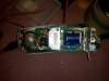
Since you have a capacitor tester . . . see if 0 decimal 68 ufd or 6.8 ufd is being its magical value ?
Seems like more BULK size would be needed, for that units voltage rating . . .in it being a 6.8 ufd..

BUT the actual function of this capacitor is in it being a series voltage dropping element..
Thereby with an AC impedance of 4680 ohms for a value of .68 , that would let about 50 mils of current be outputted.
Now with 6.8 ufd and its AC impedance equivalency of 468 ohms PLUS a companion 100 ohm series resistor,
THAT combo would let about 500 ma of current through . . . . .more than is needed, to then rectify and filter, in order to be able to snap the 24VDC relay in ,
Plus, there is being a miniscule amount being needed for the secondary power supply level . . . . for the rest of the board.
I'm thereby expecting it to be Decimal 68 ufd.

73's de Edd
 
Last edited:

bushtech

Sep 13, 2016
1,025
Joined
Sep 13, 2016
Messages
1,025
Correct St Edd thanks
Esr meter reads 0.78micro farad

Fyi on the switch's box it reads 5A 1000W
 

bushtech

Sep 13, 2016
1,025
Joined
Sep 13, 2016
Messages
1,025
I have ordered the diodes and cap. Will let you know if that sorted it
 

bushtech

Sep 13, 2016
1,025
Joined
Sep 13, 2016
Messages
1,025
St. Edd
1."THAT combo would let about 500 ma of current through . . . . .more than is needed, to then rectify and filter, in order to be able to snap the 24VDC relay in ,"
According to a datasheet I found for that NT72C -S10 the relay is actually 12VDC.

2. I replaced the 4 diodes with smd 1N4007's and the cap. Using your back and wallet saver test lamp it's still not working as far as I can see. Trying this setup on my undamaged switch the led starts flashing. Trying it on the damaged one I get no flashing led. And I checked the led to see if it works.

3. My test lamp never lights up in these tests. Is that correct? Is that because there is no current flow out of the board to the light so there is no big current flow through the test lamp?
 

bushtech

Sep 13, 2016
1,025
Joined
Sep 13, 2016
Messages
1,025
Just to increase my electronics knowledge. Here is a photo of the daughter board connection on my switch:

Daughter board.jpg
How do you remove this board. Is it a plug in or do you need to unsolder it? If so, where is the correct place to unsolder it, bottom of motherboard or top of daughter board. Sorry, bit of a stupid question but I've never dealt with something like this and I hate breaking things due to ignorance.
 

73's de Edd

Aug 21, 2015
3,622
Joined
Aug 21, 2015
Messages
3,622
Sir bushtech . . . . .

Oh how lucky you are . . .to have a GOOD board to compare against .

According to a datasheet I found for that NT72C -S10 the relay is actually 12VDC.
That round GREEN label precluding my being able to read that relays suffix . . .I had guestimated it in ending.as NT72C -240.
With no LED activity on the "BAD" board as compared to the "GOOD" board producing LED action, looks like you need to check for DC voltage presence across the power supply's main BLUE electrolytic and also get the levels at the ORANGE and CHARTREUSE ,IF there was an initial DC voltage presence back at the BLUE electrolytic.
If there IS being a socketing between the Main PCB and that daughter board, looks like their union would be at the top of black plastic upper "sockets" , mating to the very bottom of the daughter board.

Very slightly lift on a corner, to see if it raises up just a wee bit . If no movement expect to use generous rosin flux application to the solder joints and then use solder wick to wick off and desolder the BOTTOM pins on the main PCB or . . . . .use of a little less desirable solder sucker.
PROBABLY . . .that RF and decoding daughter board would be the very last suspect to consider to be at fault and then have to work with.

73's de Edd
 
Last edited by a moderator:
Top