Maker Pro
Maker Pro

what do i need to make a motor timer/controller?

sammyboy

Aug 11, 2011
23
Joined
Aug 11, 2011
Messages
23
hi
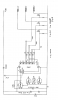
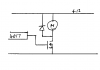
i need to make a circuit that has 7 or 8 outputs and each output must be 12v dc and each output must stay on for 2 to 3 seconds to drive a 12v dc motor and then the next output must do the same until all outputs have been on.

the cheapest and easiest for someone with not much electronics knowledge would be best.

guessing i need some completed circuit boards like these? -

http://www.ebay.co.uk/itm/USB-8-Cha...ltDomain_0&hash=item27aea30187#ht_8405wt_1189

http://www.ebay.co.uk/itm/8-Relay-B...ltDomain_0&hash=item27ae6fd771#ht_6367wt_1189

http://www.ebay.co.uk/itm/Arduino-M...Supplies_ET&hash=item3a6a246f46#ht_2812wt_956


please help if you can.

sam
 

sammyboy

Aug 11, 2011
23
Joined
Aug 11, 2011
Messages
23

duke37

Jan 9, 2011
5,364
Joined
Jan 9, 2011
Messages
5,364
Have a look at the CMOS 4017 Johnson counter, this could be clocked at 2 second intervals and the outputs could switch MOSFETs to drive the motors.
 

sammyboy

Aug 11, 2011
23
Joined
Aug 11, 2011
Messages
23

duke37

Jan 9, 2011
5,364
Joined
Jan 9, 2011
Messages
5,364
Do you have one motor or a plethora?
I attach a diagram of a traffic light sequencer which I made recently, this shows the basic idea. You will need to alter the timing on the 4093 oscillator to suit yourself and you will not need any of the 1N4148 diodes, just take an outout from the 4017 to the FET.
You will need a 'catching' diode across your motor(s) to absorb spikes.

The oscillator frequency is aproximately 2.7/(R * C) or on time is (R * C)/2.7.
A reset may be desirable in your case to start the sequence properly.
The motor(s) would be connected between the +12V and the FETs.

I made the sequencer on matrix (Vero) board.
Sorry about the orientation of the diagram but I do not know how to alter it.
 

Attachments

  • Sequencer.png
    Sequencer.png
    16.1 KB · Views: 327

(*steve*)

¡sǝpodᴉʇuɐ ǝɥʇ ɹɐǝɥd
Moderator
Jan 21, 2010
25,510
Joined
Jan 21, 2010
Messages
25,510
Yes and no.

The circuit looks like a 555 and 4017 combination which will broadly do what you ask.

However the individual outputs cannot switch a load as large as a relay. You would need to replace each LED with a transistor (possibly a resistor, and then the relay, which in turn would need a diode across it to prevent damage to the reansistor when the relay switches off.
 

sammyboy

Aug 11, 2011
23
Joined
Aug 11, 2011
Messages
23
Yes and no.

The circuit looks like a 555 and 4017 combination which will broadly do what you ask.

However the individual outputs cannot switch a load as large as a relay. You would need to replace each LED with a transistor (possibly a resistor, and then the relay, which in turn would need a diode across it to prevent damage to the reansistor when the relay switches off.

yes your right and i have found a drawing of a light sequencer that has been modified to run relays and in turn run 120vac bulbs but i guess this will work for 12vdc relays just the same.
problem with this one is that its 9 vdc and not my desired 12vdc and it has no timer wired in the circuit.
so if anyone can adjust this to my requirements that would be great?

http://i206.photobucket.com/albums/bb49/samo1591/Picture3.png
 

(*steve*)

¡sǝpodᴉʇuɐ ǝɥʇ ɹɐǝɥd
Moderator
Jan 21, 2010
25,510
Joined
Jan 21, 2010
Messages
25,510
You could run that from 12V.

However, you need to place a resistor between the putputs of the 4017 and the transistor's bases (4k7 would be fine) and place a normal relay etween the +ve supply and the collector of the transistor. The emitter is then grounded without the resistor shown there. And you nust remember to place a diode across the relay coil.

There's an example here. Note that it has an additional LED and resistor to provude a visual indication that the relay is energised.
 

sammyboy

Aug 11, 2011
23
Joined
Aug 11, 2011
Messages
23
You could run that from 12V.

However, you need to place a resistor between the putputs of the 4017 and the transistor's bases (4k7 would be fine) and place a normal relay etween the +ve supply and the collector of the transistor. The emitter is then grounded without the resistor shown there. And you nust remember to place a diode across the relay coil.

There's an example here. Note that it has an additional LED and resistor to provude a visual indication that the relay is energised.

thanks but i cant get your link to work.
if i can ask whats a normal relay, +ve supply and collector of the transistor?
Maybe your link makes it easy for me to understand.
 

jackorocko

Apr 4, 2010
1,284
Joined
Apr 4, 2010
Messages
1,284
a normal relay is just what you think it is. They make other special kinds that steve is trying to say you will not need. If you are using a 12Vdc supply then you will need relay with coils that work on 12Vdc.
 

(*steve*)

¡sǝpodᴉʇuɐ ǝɥʇ ɹɐǝɥd
Moderator
Jan 21, 2010
25,510
Joined
Jan 21, 2010
Messages
25,510
Here is the important image...

Clap.jpg
 

sammyboy

Aug 11, 2011
23
Joined
Aug 11, 2011
Messages
23
that looks super complicated though probably not for everyone else on here.
ive had some component help with the previous light diagram adjusted to work with relays.

ive adjusted the diagram using paintbrush (if you couldnt guess) and the wiring im unsure about.
please feel free to edit the diagram to make it more correct or even simpler for me to understand.

http://i206.photobucket.com/albums/bb49/samo1591/relaysequencefordummies.jpg

thanks again.
 

duke37

Jan 9, 2011
5,364
Joined
Jan 9, 2011
Messages
5,364
1. The output from the 4017 is wrong, either the relay pin 86 should go to earth or you should use the use the circuit in the previous post.

2. The 470R resistors will severely restrict the motor power, is this what you want?

3. It would be simpler, smaller and probably cheaper to use a FET to switch the motor as shown in my earlier diagram. A IRF540A could manage over 5A with ease.

Duke
 

Attachments

  • MotorDrive.png
    MotorDrive.png
    2.2 KB · Views: 207

sammyboy

Aug 11, 2011
23
Joined
Aug 11, 2011
Messages
23
1. The output from the 4017 is wrong, either the relay pin 86 should go to earth or you should use the use the circuit in the previous post.

2. The 470R resistors will severely restrict the motor power, is this what you want?

3. It would be simpler, smaller and probably cheaper to use a FET to switch the motor as shown in my earlier diagram. A IRF540A could manage over 5A with ease.

Duke

Ah yeah ive put the + and - the wrong way round for the motors and relays is that what you meant?
I would happy to use any diagram but i cant read diagrams so most of it doesn't mean much to me but im trying to learn through trial and error.
ive made some alterations to the diagram adding a mosfet instead of one of the relays as an example for how all the relays would be swapped out plus i swapped around the polarity.
so if someone could check it i would be grateful.

http://i206.photobucket.com/albums/bb49/samo1591/relaysequencefordummiesnew.png
 

sammyboy

Aug 11, 2011
23
Joined
Aug 11, 2011
Messages
23
dont think i need to power the mosfets as i think they can be powered from the board but how?
 

duke37

Jan 9, 2011
5,364
Joined
Jan 9, 2011
Messages
5,364
You are making life complicated!
You do not need the 2N3904.
You do not need power to the FET, it is just like a switch in this application controlled by the voltage on the gate.
The power for the motor comes from the 12V source.
The diode should go across the motor, you have shown it shorted.
Diagrams are easier to understand if you keep earth at the bottom and the positive line at the top.
 

(*steve*)

¡sǝpodᴉʇuɐ ǝɥʇ ɹɐǝɥd
Moderator
Jan 21, 2010
25,510
Joined
Jan 21, 2010
Messages
25,510
That's fine, but you may find it won't work.

Noise from the motors is still quite likely to upset the 555 or the 4017.

You will need to (or be best advised to) split the power to the motors and the power to the logic. Although they can both come from the same source, the power to the logic should be via a low value resistor (say 100 ohms) and then have a capacitor to earth (say 100uF). This will prevent the noise and spikes generated from the motors reaching the more sensitive electronics.

You will notice that your circuit is almost identical to the one I showed you, other than you have a mosfet instead of a bipolar transistor and you drive the motor rather than a relay.

Incidentally, in the circuit where you showed a normal relay in place of the Solid state relay, your connections need to be rotated by 90 degreed anti clockwise. In the SSR the leftmost 2 connections power the equivalent of the coil (the resistor is in series with this as it is actually a LED) and the connections tot he right are the normally open contacts.
 

sammyboy

Aug 11, 2011
23
Joined
Aug 11, 2011
Messages
23
thanks steve, would love to of used your diagram but i couldnt understand it as i dont know what everything is so i spent ages trying to understand the one i had originally and started editing it.
so the symbol ive drawn from the motors are LEDS? what should they be?

ive edited it with resistors, capacitors and added the 100kΩ trimmer though i dont know where connection 2 on the trimmer should go?

comment please

http://i206.photobucket.com/albums/bb49/samo1591/relaysequencefordummiesnewedited2.png
 
Top