Hello, how is everybody.
I am currently designing an interface between a RMS (Radio Management System) and some radios.
One of the things my device do is turning them ON using a relay (this relay ahs voltage suppression) the problem is that the relay required consumes more current than the current my RMS outputs can handle nominally.
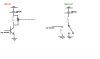
my solution is to use a bus configuration device that uses darligton BJT transistors with a open collector output, the idea is to saturate the darlington base and connect the relay with the collector (as described in the attached file), I am adding a voltage suppressor for possible transient voltage in the relay coil.
The problem is that my design was rejected, they said that instead of doing that we should use a smaller relay to turn a bigger one ON and OFF, according to them that ay we wont need the voltage suppressor.
Do you guys know if thats true? I though voltage transients in inductors were related just with de-energizing the relay, not with the use of semiconductors, but i am not an expert so I was wondering if some could help me with this.
I am currently designing an interface between a RMS (Radio Management System) and some radios.
One of the things my device do is turning them ON using a relay (this relay ahs voltage suppression) the problem is that the relay required consumes more current than the current my RMS outputs can handle nominally.
my solution is to use a bus configuration device that uses darligton BJT transistors with a open collector output, the idea is to saturate the darlington base and connect the relay with the collector (as described in the attached file), I am adding a voltage suppressor for possible transient voltage in the relay coil.
The problem is that my design was rejected, they said that instead of doing that we should use a smaller relay to turn a bigger one ON and OFF, according to them that ay we wont need the voltage suppressor.
Do you guys know if thats true? I though voltage transients in inductors were related just with de-energizing the relay, not with the use of semiconductors, but i am not an expert so I was wondering if some could help me with this.