Maker Pro
Maker Pro

Vintage stereo receiver re-lamp with LEDs

OJ Bartley

Nov 22, 2012
20
Joined
Nov 22, 2012
Messages
20
Right, I do remember reading that now... so would this be the correct way to wire 3 LEDs?

mixedcircuit2.jpg


(I love this CircuitLab website, makes it very easy to play with configuration)
 

duke37

Jan 9, 2011
5,364
Joined
Jan 9, 2011
Messages
5,364
The top circuit would be correct if the blue led was connected the right way round

You have been told not to connect leds in parallel so why include the second diagram?
 

KJ6EAD

Aug 13, 2011
1,114
Joined
Aug 13, 2011
Messages
1,114
I should have been more clear when I said you have to run the LEDs in parallel. You put them in parallel legs of the circuit but each has it's own limiting resistor as in your top circuit. You can add as many resistor and two diode legs in parallel as your supply will accommodate but you shouldn't mix LED types within the leg so 2 blue or 2 white, not 1 of each.

attachment.php


Have you measured the supply voltage?
 

Attachments

  • LEDs on AC.jpeg
    LEDs on AC.jpeg
    13.6 KB · Views: 700
Last edited:

(*steve*)

¡sǝpodᴉʇuɐ ǝɥʇ ɹɐǝɥd
Moderator
Jan 21, 2010
25,510
Joined
Jan 21, 2010
Messages
25,510
With AC it gets more complex. (And that is at least 1 reason why the guide doesn't talk about it).

For AC, if you have 2 diodes in anti-parallel, you can consider this to be 1 diode. So it has its own resistor. That would be the two white LEDs.

Then the Blue LED is on its own. I think if we go back to the start of this thread we were talking about how to do that. It would be best to have a normal diode in series with it. Alternatively, another blue LED in anti-parallel.

Also remember that if you have an AC voltage source, show it as such or we will assume it is what you have shown -- a DC source.
 

OJ Bartley

Nov 22, 2012
20
Joined
Nov 22, 2012
Messages
20
Well, I was able to find my multimeter and measure voltage across one of the bulb sockets tonight. It flickered a little between 7 and 8v. Then I touched a probe to the chassis and blew the fuse for all the lighting. Which is a pain because it is on the bottom of the unit and soldered directly to it instead of in a regular socket. One more item to clean up I guess, and another lesson learned.

Sorry about the voltage source in the diagrams, I just picked one that had + and - without knowing what it stood for.

It looks like I will either have to put a pair of each white and blue in anti-parallel, or just go back to my original pair of whites and forget the blue.

2pairsled.jpg
 

OJ Bartley

Nov 22, 2012
20
Joined
Nov 22, 2012
Messages
20
I just wanted to run my options past the forum for confirmation. I have broken it down into 3 different scenarios.

Scenario 1: 2 white LEDs

2white.jpg


The 2 LEDs are run in anti-parallel to counteract 60Hz flicker.

Scenario 2: 2 white LEDs, 1 blue LED with blocking diode Edit: diagram fixed

2white1blue2.jpg


R2 increased to deal with ~0.6V increase from extra diode. This configuration may leave more visible flicker.

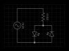
Scenario 3: 2 white LEDs, 2 blue LEDs, each pair run in anti-parallel

2white2blue.jpg


Probably my best option if I can fit it all into a small enough form factor. Gives the most light, spread out evenly, and each colour has compensation for flicker.

Now that the components are sorted out, I need to figure out how to get the circuits to fit into standard 5mm fuse sockets in the receiver. Is it reasonable to think I can make my own rigid loop connectors, or should I disassemble a bunch of fuses to get their end caps to use? The latter sounds like a lot of complication that I would rather avoid if possible, and I don't know how sturdy I could make them.
 
Last edited:

BobK

Jan 5, 2010
7,682
Joined
Jan 5, 2010
Messages
7,682
Scenario 2 is wrong. The white LEDs are not protected from reverse voltage. Move the 1N4004 to connect between the AC source and the rest of the circuit, so that the current flows to all of the LEDs through the diode. Or, put the two white LEDs in antiparallel and leave the blue + diode as is.

Bob
 

OJ Bartley

Nov 22, 2012
20
Joined
Nov 22, 2012
Messages
20
Thanks Bob, I meant to run those in anti-parallel. I fixed the original one above (I think?) and put together this layout, which I think would be preferable to reduce the flicker of the white LEDs...

Scenario 2 ALTERNATE LAYOUT: 2 white LEDs, 1 blue LED with blocking diode

2white1bluealtlayout.jpg
 
Last edited:

(*steve*)

¡sǝpodᴉʇuɐ ǝɥʇ ɹɐǝɥd
Moderator
Jan 21, 2010
25,510
Joined
Jan 21, 2010
Messages
25,510
Yep, that looks fine
 

OJ Bartley

Nov 22, 2012
20
Joined
Nov 22, 2012
Messages
20
Thanks Steve, and everyone else who contributed. I really appreciate the help, since this is all pretty new to me, but I wanted to learn how to do it instead of just buying something premade. I think that's about it for now, but I'll definitely be back to post the work in progress, probably sometime over Christmas.

It's great that we have places like ElectronicsPoint where someone can go and ask for help, and learn a ton from people who really know what they're doing.
 

OJ Bartley

Nov 22, 2012
20
Joined
Nov 22, 2012
Messages
20
Just thought I'd pop back in to show that all of your great advice hasn't gone to waste. I have most of my supplies now (a few things still haven't arrived), but I had enough to put together a test circuit and play around some.

This is a version of the 2 white and 2 blue without the blocking diode (don't have them yet). Everything seems to work well, the light should be plenty bright enough for what I need (I tried 240 ohm and 270 ohm resistors which both looked good). The LEDs don't seem to flicker, which is great. Now I just need the last few parts and I can try one on an actual small circuit board.

testing3.jpg


testing4k.jpg


Thanks again, everyone! I'll update when I get any more progress worth posting.
 

OJ Bartley

Nov 22, 2012
20
Joined
Nov 22, 2012
Messages
20
I've made a little more progress, and am very happy with my first steps using what I learned here. Granted, this was just replacing a single LED, but my projects are growing more ambitious as I go. Here's a link to a post where I documented the first little project.

http://www.audiokarma.org/forums/showpost.php?p=6423939&postcount=34

Oh, and I later realized that my "no flickering" comment from above was a bit silly, because they wouldn't flicker using a DC power source like a battery. There was some minor flicker when I used an AC source.
 

(*steve*)

¡sǝpodᴉʇuɐ ǝɥʇ ɹɐǝɥd
Moderator
Jan 21, 2010
25,510
Joined
Jan 21, 2010
Messages
25,510
It looks like you are connecting LEDs in parallel on your board. That is generally a bad thing. You should have enough voltage from your battery to place them in series (it will also make your battery last much longer)

Also it is best/conventional to have +ve at the top of your breadboard and -ve at the bottom.
 

OJ Bartley

Nov 22, 2012
20
Joined
Nov 22, 2012
Messages
20
Hi Steve, I was just hooking up to the battery to test my connections and see if things worked. It will be connected to I think about 8V AC when in the receiver. I'll be using this layout from page 2:

2white2blue.jpg


Good idea to separate the + and - leads, I think I actually did that for my later testing, but I'll keep it in mind.
 

(*steve*)

¡sǝpodᴉʇuɐ ǝɥʇ ɹɐǝɥd
Moderator
Jan 21, 2010
25,510
Joined
Jan 21, 2010
Messages
25,510
OK, it just looked like all the LEDs were lit. And that is wrong if you've connected them this way. With a DC source, only one of each pair should light. Reverse the battery and the other one from each pair should light up.
 

OJ Bartley

Nov 22, 2012
20
Joined
Nov 22, 2012
Messages
20
Actually, you are exactly right, and that confused me at first when I wired them with 2 in anti-parallel. I flipped the LEDs that didn't light to make sure they weren't dead, but when I went to the AC power source I made sure to flip them back.

In my next post at AK I showed it hooked up to the receiver's AC power source, wired properly. In this setup, I did see the flicker.

http://www.audiokarma.org/forums/showpost.php?p=6434409&postcount=35

I know, my little circuit board is a disaster, but this was my first crack at it.
 

OJ Bartley

Nov 22, 2012
20
Joined
Nov 22, 2012
Messages
20
Here's a little update just to show I'm still working on this and your advice didn't go to waste. I managed to build one working circuit, as sloppy and awkward as it is.

finalled1.jpg


finalled3.jpg


I should really look into etching a proper PCB which would make things a lot cleaner and faster in the long run.
 
Top