Maker Pro
Maker Pro

VCLFO debugging

darren adcock

Sep 26, 2016
463
Joined
Sep 26, 2016
Messages
463
Hi all, for the life of me i can't figure out what mistake i've made putting together a MFOS VCLFO. Usually when i get readings like this I've done somert rediculous, but i can't seem to find my obvious mistake and was hoping you guys could help please? I include meter readings of transistors and IC's. plus off each pot leg. One stick point is that on the schematic MFOS says C11 should be "C11 (main oscillator integrator cap) should be a temperature stable type of cap (polystyrene, polycarbonate, etc.).
All others can be ceramic or film." however the soundtronics kit uses a ceramic cap here.

Here are the readings, I'll add below circuit shots and schematic. All readings are taken with pots turned full clockwise.

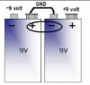
Voltage source is 12v

2N3904
Q1; E = 8.46/ B = 8.93/ C = 8.53
Q2; E = 8.46/ B = 8.8/ C = 8.4
Q6; E = 11/ B = 11 / C = 12

2N3906
Q3; E = 8.85/ B = 8.40/ C no reading

MPF102
Q4; D = 10/ S = 6.7/ G = 1.3
Q5; D = 11/ S = 11/ G = 11

TL082
U2; 1 = 11. 2 = 9. 3 = 8. 4 = -. 5 = 9. 6 = 6.3. 7 = 11. 8 = 12.
U4; 1 = 1.3 2 = 9. 3 = 8. 4 = - 5 = 9. 6 = 6.3. 7 = 11. 8 = 12
U5; 1 = 8.6 2 = 9. 3 = 8. 4= -. 5 = 9. 6 = 8.4. 7 = 9. 8 = 12
U6; 1 = 11. 2 = 7.5. 3 = 8.6. 4 = - 5 = 9 6 = 9. 7 = 8. 8=12

LM13700N.

U3; 1 = no reading. 2 = 2. 3 = 9. 4 = 9. 5 = 1.5. 6 = -. 7 = 300mv (rises up to here from around 20mv). 8 = 0.4v.
9 = 9.4. 10 = 11. 11 = 12. 12 = 11. 13 = 9. 14 = 9. 15 = 2. 16 = 1.1

LF442CN
U1; 1 = 9. 2 = 9. 3 = 9. 4 = -. 5 = 9. 6 = 9. 7 = 9. 8 = 12

Fine Potentiometer.
1 = -12. 2 = 12. 3 = 12

Course Potentiometer.
1 = no reading. 2 = 9. 3 = 12

PWM Potentiometer.
1 = 4. 2 = 7.4. 3 = 8

mfos schematic vclfo.gif WIN_20170721_14_32_14_Pro.jpg WIN_20170721_14_32_40_Pro.jpg
 
Last edited:

kellys_eye

Jun 25, 2010
6,514
Joined
Jun 25, 2010
Messages
6,514
Voltage source is plus AND negative 12V

None of your readings show -ve volts. Are you using 0V as the reference? Have you got a proper split-rail 12V supply?
 

kellys_eye

Jun 25, 2010
6,514
Joined
Jun 25, 2010
Messages
6,514
Pin 4 of the TL082 is showing as -0.5V

They should be -12V. Is the -12V line ok?
 

kellys_eye

Jun 25, 2010
6,514
Joined
Jun 25, 2010
Messages
6,514
I can see some potential short circuits around the IC pins (U2) caused by inefficient cleaning/poor soldering.
 

darren adcock

Sep 26, 2016
463
Joined
Sep 26, 2016
Messages
463
cheers.

my mistake for not making my readings clear. I've edited post now so it doesn't look like pin 4 is 0.5v.

My power supply reads 12v.
 

darren adcock

Sep 26, 2016
463
Joined
Sep 26, 2016
Messages
463
I can't find any shorts around U2. Been through and changed all IC's now. And still the same.
 

kellys_eye

Jun 25, 2010
6,514
Joined
Jun 25, 2010
Messages
6,514
Not interested in what your power supply reads - your DATA shows pin 4 of U2, U4, U5 and U6 as well as pin 6 of U3 etc all reading -0.5V.

They should all be -12V
 

darren adcock

Sep 26, 2016
463
Joined
Sep 26, 2016
Messages
463
I'm sorry Kelly's eye I don't understand.

I don't know how to get my DMM to read -12v? Am I taking readings incorrectly?

I wrote pins 4 of TL082's as "-" as I didn't think it would work putting my probe from DMM onto them. When I put meter accross pins 4 and 8 it reads 12v. If that is helpful. I feel I am clearly misunderstanding something here. Thanks for your patience.
 

kellys_eye

Jun 25, 2010
6,514
Joined
Jun 25, 2010
Messages
6,514
Across 4 and 8 it should read 24V.

Put your meter black lead on 0V (pin2 of U4 will do) and then measure pins 8 and 4 of the same chip using the red lead.

Pin 8 should show +12V and pin 4 will show -12V. If not, get back to us.

If you put your black lead on pin 4 and the red on pin 8 the meter should read 24V.

What are you using to power the circuit?
 

kellys_eye

Jun 25, 2010
6,514
Joined
Jun 25, 2010
Messages
6,514
That power supply won't work. It is only a SINGLE RAIL supply (3-15V DC).

You need a DUAL RAIL power supply that will provide "positive-gound-negative" supply lines.

Get TWO AA battery holders (that take 8-cells) to provide two lots of 12V from a battery source.

Connect the positive of one holder to the negative of the second holder. This is your common (zero or ground) connection. The positive pin that's left becomes +12V (with respect to the common ground) and the negative pin that's left becomes -12V with respect to the common ground.

In other words you now have a power supply with THREE wires. +12V - 0V and -12V. THIS is what you need to power your circuit.

Here's a picture of a similar arrangement but using two 9V batteries - you want 12V
 

Attachments

  • Batteries.png
    Batteries.png
    32.1 KB · Views: 40

darren adcock

Sep 26, 2016
463
Joined
Sep 26, 2016
Messages
463
Thank you. I will get on this. I am going to try and buil alot of the MFOS range. So I may just invest in a dual rail bench supply. I'm annoyed i missed this, i recently built two of the noise makers off there and they both required dual rail with a ground.

Cheers for your time here.
 

davenn

Moderator
Sep 5, 2009
14,264
Joined
Sep 5, 2009
Messages
14,264
. I'm annoyed i missed this,

a little trap for young players ;)

but I have to ask, when you looked at the schematic, where did you think all those -12V lines went to ?
I have labelled a few of them in red circiles

upload_2017-7-22_8-40-48.png
 

darren adcock

Sep 26, 2016
463
Joined
Sep 26, 2016
Messages
463
Haha... yes a trap indeed, now them red circles are taunting me further! I honestly just thought they went to the circuit board and I'd connect a dc supply to the board. Nope. Just ordered the DC to Bipolar board off soundtronics. After all that meter checking, typing, then even missing you asking about dual rail in first message... grrrrr. Thanks again.
 

darren adcock

Sep 26, 2016
463
Joined
Sep 26, 2016
Messages
463
I guess the thing is also, because I've changed tack and am now building modular I just didn't see that a power supply of this nature was gonna be necessary. Learning learning. I'd swap that fine art degree for EE physics right now!
 

darren adcock

Sep 26, 2016
463
Joined
Sep 26, 2016
Messages
463
Hi again. Just a few questions regarding safety. I've just built the mfos wall wart to bipolar power supply. I am yet to plug it in. It requires a 12v ac power supply with a maximum of 1000ma. I am not the most attentive of person and can easily make mistakes. Should I be building this? Is there risk of electric shock? On MFOS site it says it's for advanced builders, i'm definitely not that just kinda stumbling through their range and grasping understanding where I can. I've only made the single board noise makers from MFOS which i found relatively easy but it doesn't mean I understand them, the noise toaster was a good build as it came with a book which i read and feel i've got an ok understanding of it.

Best

Darren
 

kellys_eye

Jun 25, 2010
6,514
Joined
Jun 25, 2010
Messages
6,514
You built the LFVCO - the wall wart isn't any more complicated, go for it.

There is no shock risk from the 12V AC power pack. Providing you put the parts in the 'right way around' then it will work.
 
Top