Maker Pro
Maker Pro

using mosfets to switch a 12 volt 2 amp load

Rusty66

Sep 17, 2013
9
Joined
Sep 17, 2013
Messages
9
Hi everyone, Im just a newbie hobbyist trying to work out what im doing wrong...

Ive got some 3 watt LED's here that i am flashing using an N channel mosfet (BUZ90), i am using a 555 circuit as a flasher. The 3 watt leds all have their own current circuitboard and i am switching 6 of them on & off in parrallel using the circuit. (similar to emergency vehicle lights)

The array of lights operates at 12 volts at approx 1.5 Amps.

The problem I am having is the mosfets are getting hot. The last lot failed, so I upgraded.

Im trying to keep the circuit board size small as well, so I dont really want to go any bigger size wise. I thought the size of these mosfets would have handled that load well..

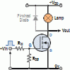
There is a pic of the circuit below.. This is how I have wired up the mosfet..

Any ideas to where I am going wrong?

Should I scrap the mosfets and use something else???

I look forward to your suggestions! Please be gentle as I am a newbie!

Rusty
 

Attachments

  • tran21.gif
    tran21.gif
    6.1 KB · Views: 511

(*steve*)

¡sǝpodᴉʇuɐ ǝɥʇ ɹɐǝɥd
Moderator
Jan 21, 2010
25,510
Joined
Jan 21, 2010
Messages
25,510
What are the values of those resistors, and what is the input voltage to the gate of the mosfet?

Excessive heat is almost certainly a symptom of the mosfet not being turned on hard enough.
 

(*steve*)

¡sǝpodᴉʇuɐ ǝɥʇ ɹɐǝɥd
Moderator
Jan 21, 2010
25,510
Joined
Jan 21, 2010
Messages
25,510
The datasheet confirms what I feared.

This is a high voltage mosfet with a high Rds(on). With 5V at the gate, it will end up dissipating about 5W. Without a heatsinlk that's too much. Even with 15V at the gate, the dissipation is going to be a couple of watts.

Add to that, if you're flashing them and your gate resistor is too low, or your driver can't supply a lot of current, you'll be adding switching losses.

In addition to my questions above, tell us more about the circuit driving this and the rate you're flashing the lights.

Oh, and lights, not LEDs. There will alos be a swith-on transient. This may be mitigated by slower turn-on of the mosfet, but it's an issue either way.
 

Rusty66

Sep 17, 2013
9
Joined
Sep 17, 2013
Messages
9
OK, Rin is 270 ohm (this circuit was originally designed to drive a normal LED)

Rgs is 100K

The circuit diagram is only as an example of how I wired my LEDS using the mosfet..

I have a small clip on heatsink on the mosfet.. they still get plenty warm..

The circuit driving them is just like an emergency vehicle warning light. It has multiple flash modes, nothing really quick tho. The output of the chip runs thru the 270 ohm resistor to the gate of the mosfet. I did try bypassing the 270 ohm resistor, but it made no difference to the heat generated.. I also used the inductive load diode to see if that made a difference.. It didnt!
 

(*steve*)

¡sǝpodᴉʇuɐ ǝɥʇ ɹɐǝɥd
Moderator
Jan 21, 2010
25,510
Joined
Jan 21, 2010
Messages
25,510
You don't mention the voltage at the gate, but that's not too important.

I would tend to look for a logic level mosfet capable of about 20A to 30A and rated at about 40V.

See this post. CHange the parameters as suggested above and I'd recommend a device capable of between 20W and 100W just so you're not going to stress it.

Since you're not flashing it quickly, there is no need to balance the Rds(on) and gate capacitance. Look for something cheap with an Rds(on) of 0.1 ohm or lower.

This is an option. It seems to come up a bit. There is also the plastic version.
 

Rusty66

Sep 17, 2013
9
Joined
Sep 17, 2013
Messages
9
Steve your help has been fantastic.. Looking at the flasher PCB Its a 12F675 chip that supply's the output for the mosfet.. so the 270 ohm resistor should be removed / bypassed?

as I said, I know im in a little over my depth here, but this is how one learns yeah!

Thanks again for all your help!
RUSTY
 

(*steve*)

¡sǝpodᴉʇuɐ ǝɥʇ ɹɐǝɥd
Moderator
Jan 21, 2010
25,510
Joined
Jan 21, 2010
Messages
25,510
Choose the resistor that limits the current to the max the device can supply. If that is 20mA at 5V, use a 250 ohm resistor -- so 270 ohms is about right.

You could reduce it because the PIC outputs are not going to be too fussed, but I don't think there's any real point.
 

(*steve*)

¡sǝpodᴉʇuɐ ǝɥʇ ɹɐǝɥd
Moderator
Jan 21, 2010
25,510
Joined
Jan 21, 2010
Messages
25,510
Let us know how you get on with this.
 

Rusty66

Sep 17, 2013
9
Joined
Sep 17, 2013
Messages
9
put the F13N06L's in today & its working a treat! Mosfets only getting luke warm.

Thanks for all your help,
Ill try and post a video later today!

Cheers

Rusty
 

(*steve*)

¡sǝpodᴉʇuɐ ǝɥʇ ɹɐǝɥd
Moderator
Jan 21, 2010
25,510
Joined
Jan 21, 2010
Messages
25,510
Great news.
 

Rusty66

Sep 17, 2013
9
Joined
Sep 17, 2013
Messages
9
excuse the crappy phone video, but here is the finished item working :)


thanks again for your help!

Rusty
 

(*steve*)

¡sǝpodᴉʇuɐ ǝɥʇ ɹɐǝɥd
Moderator
Jan 21, 2010
25,510
Joined
Jan 21, 2010
Messages
25,510
It certainly looks the part :)

Well done.
 
Top