Maker Pro
Maker Pro

ultrasonic sensor at 40 KHz

himanshu0128

Mar 21, 2016
10
Joined
Mar 21, 2016
Messages
10
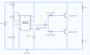
  • hi guys..just need a little help. i made a receiver circuit(shown in the image) for the ultrasonic sensor at 40 KHz. it works fine and my max. output is 3V. However I want to replace the transistor with opamp. Pls suggest some circuit.
  • i have already tried using LM741 but it dint give desired results to due its limited bandwith gain..Kindly suggest a circuit using TL081 keeping in mind the 40KHz signal and desired gain of atleast 75.
  • upload_2016-3-21_12-28-40.png
  • The receiver module is connected between the capacitor(+pin) and ground(-pin).
 

Attachments

  • upload_2016-3-21_12-26-38.png
    upload_2016-3-21_12-26-38.png
    32.6 KB · Views: 85

Colin Mitchell

Aug 31, 2014
1,416
Joined
Aug 31, 2014
Messages
1,416
What gain are you getting.

Increase the 48k to 470k and 18k to 220k
 
Last edited:

himanshu0128

Mar 21, 2016
10
Joined
Mar 21, 2016
Messages
10
i m getting a gain of around 100 with this. But I want to replace it with an OPAMP only..
 

himanshu0128

Mar 21, 2016
10
Joined
Mar 21, 2016
Messages
10
becoz my GUIDE insists for it..
also I will have to interface it with LED display and arduino later on..
Please help me..
 

AnalogKid

Jun 10, 2015
2,893
Joined
Jun 10, 2015
Messages
2,893
What is a GUIDE? Is this a homework problem?

That is a gain-bandwidth of 3 million. That's a lot. The TL081 datasheet says this is the max value for the part, so it would be operating open loop (not god). You will get better results with a compound amplifier, basically two amps in series. With a 10 V single supply and normal AC coupling techniques, two standard AC non-inverting opamp gain stages in series will work. TL081 datasheet, figure 27 (AC distribution amplifier), left half.

ak
 

himanshu0128

Mar 21, 2016
10
Joined
Mar 21, 2016
Messages
10
This is not a homework problem. this is my project..using amplifiers results in my received sine wave distorted to triangular wave..so its not working out.
nd gain bandwidth of 1 MHz is less for me because practically i cannot get more than 10 gain.
my receiver receives signal of amplitude less than 20 mV.
 

Colin Mitchell

Aug 31, 2014
1,416
Joined
Aug 31, 2014
Messages
1,416
"This is my project..using amplifiers results in my received sine wave distorted to triangular wave..so its not working out.

And gain bandwidth of 1 MHz is less for me because practically I cannot get more than 10 gain.
my receiver receives signal of amplitude less than 20 mV."

I don't know what you are talking about.
 
Last edited by a moderator:

himanshu0128

Mar 21, 2016
10
Joined
Mar 21, 2016
Messages
10
Show circuit of transmitter
Transmitter is working fine...It Produces square pulse of 10Vp-p with 65% duty cycle..16us on time and 8us off time..Receiver circuit is a problem here..pls suggest a circuit using opamps..nt transistor..my opertaing frequency is 40KHz..
thank you
 
Top