Maker Pro
Maker Pro

Two button control for 4speed car fan

lamesh99

Sep 1, 2010
4
Joined
Sep 1, 2010
Messages
4
Hi there!
My name is Marko and as you can tell, i am new here.

Now, i'm trying to build myself, as it stands in the title, two button control for 4speed car fan;)

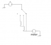
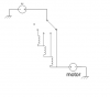
To explain, i would like to be able to raise and lower the speed of the fan. The fan already has a controlling 4-way switch, and the speed is regulated by 4 coils. I need to make a circuit that would allow me to choose between those 4 speeds, but with only 2 buttons, increase and decrease.

If a thread like this exists, please show me where it would be, and delete this one. I hope you understand what i tried to say.

Thanks in advance!
 

shrtrnd

Jan 15, 2010
3,876
Joined
Jan 15, 2010
Messages
3,876
There are several variables one would need, to design a circuit to do this (step up or down a speed with each push-button depression).
Whatever additional parts you need, would depend on the voltage and current of the fan, and the value of the coils (which are acting as resistors to control fan speed).
It may not seem important, but too much current through your added circuit, would limit it's life expectancy.
It would help if you look on the back of the fan and give info from the ID plate.
Voltage (probably 12v?)
Amperage and/or wattage.
anything else that might be of use.
You realize of course, any circuit you come up with, will require you to do some soldering? You'll have to separate those coils, to insert the stepping circuitry.
I don't have an example circuit for this, but maybe somebody else in a following post will. Another thing you'll have to think about, is where you want to mount your speed stepping circuitry, up near the fan, or down in the dash.
Sorry I don't have a circuit for you, but adding the info from the fan faceplate to your post, might help you get there.
 

Mitchekj

Jan 24, 2010
288
Joined
Jan 24, 2010
Messages
288
I'm not a car guy, but I've seen this type of project about three times now on these boards... please enlighten me: why do people need two, three, four and so on different fan speeds? Is my car suffering without the ability for me to control the fan speed?

I figure run the fan full power at all times, why would I want to slow it down? To save battery life? If the car's off, the fan's off and the engine's not actively making heat... no issue? I am missing something, I'm sure. :)

Edit: OR, are we talking about the climate control fan type stuff for the inside of the car? If that's the case, doesn't the AC/heat come with user selectable speeds already? Now I'm definitely missing something.
 
Last edited:

lamesh99

Sep 1, 2010
4
Joined
Sep 1, 2010
Messages
4
@shrtrnd:

fan is 12V, amperage or wattage yet to be discovered:) i have dissasembled the fan(motor) earlier, but i forgot to take note of those information. soldering is really not a problem, since my work includes a lot of soldering. problem is designing of the circuit, because i am not an engineer, only a technician.

board2.png
This is, i think, how the wiring looks like. Simplified, obviously.

digidash_fiattempra.jpg
The current board looks like this.

board.png
I am trying to make it look like this. (this was made in paint:), only a quick sketch)


@Mitchekj

i am talking about the AC(heating) fan. i'm trying to "pimp" my ride a little bit. ;)


I hope i gave you a bit to think about;)
Oh, and thanks for your replies, guys!
 

Resqueline

Jul 31, 2009
2,848
Joined
Jul 31, 2009
Messages
2,848
When you say 4 speed, do you mean off-low-medium-full? If so it only has two resistors and is wired like this. You'll need three relays and some logic to replace the switch.
 

Attachments

  • board2.png
    board2.png
    9 KB · Views: 210

lamesh99

Sep 1, 2010
4
Joined
Sep 1, 2010
Messages
4
actually yes, but it's off-low-higher-high-full (4 speeds). i think your diagram is actually more accurate than mine, "more correct":)
 

Resqueline

Jul 31, 2009
2,848
Joined
Jul 31, 2009
Messages
2,848
Ok, so it's 4 speeds + off (off-low-medium-high-full), making it 5 positions. You're gonna need 4 relays then. Hehe, yes, there seems to be a subtle difference to our diagrams.. ;)
Now, if only someone would step in and do the dirty work of digging up or designing a logic diagram to control those relays..
 

Attachments

  • board2.png
    board2.png
    9.5 KB · Views: 297

(*steve*)

¡sǝpodᴉʇuɐ ǝɥʇ ɹɐǝɥd
Moderator
Jan 21, 2010
25,510
Joined
Jan 21, 2010
Messages
25,510
How's this?

lamesh99, this won't work as it is, but the general principle is sound.

attachment.php


p.s. one of the reasons it won't work is that I forgot a diode across the relay coil -- but that's just a silly mistake.

The others involve debouncing the switch used as a clock source, and protecting the entire thing from transients found in cars.

edit: that only provides a 1 button off - low - med - high - full - off control. So not what you want. :( (Unless you have another button providing 4 pulses)
 

Attachments

  • fanspeed.jpg
    fanspeed.jpg
    20 KB · Views: 1,338
Last edited:

(*steve*)

¡sǝpodᴉʇuɐ ǝɥʇ ɹɐǝɥd
Moderator
Jan 21, 2010
25,510
Joined
Jan 21, 2010
Messages
25,510
Would P Channel mosfets be a better solution than relays? replacing the relay with a resistor and using the voltage swing at the collector to provide around -12V Vgs?
 

lamesh99

Sep 1, 2010
4
Joined
Sep 1, 2010
Messages
4
hmmm... okay. now, since engrish is not my "first" language, i need you guys to explain me a couple of things. first, relays.

releji.jpg
relays?

next, debouncing the switch as a clock source.

i know it must be frustrating to deal with a noob like me, especially when the noob knows nothing about technical phrases in engrish. so, thanks again for your patience:eek:

and something else, shrtrnd was on the money immediately:

(step up or down a speed with each push-button depression).
 
Top