Maker Pro
Maker Pro

Transistors as switch

abuhafss

Aug 3, 2010
348
Joined
Aug 3, 2010
Messages
348
Hi

In a 555 astable circuit, I want to induct a transistor (as an inverter switch) between points A and B such that when there is a signal at the base of the transistor the points A and B are opened, and if no signal, the points are closed. Can somebody help me how to achieve this.
 

Attachments

  • 555 astable1298515718.gif
    555 astable1298515718.gif
    4.1 KB · Views: 191
Last edited:

KrisBlueNZ

Sadly passed away in 2015
Nov 28, 2011
8,393
Joined
Nov 28, 2011
Messages
8,393
I think you want to switch your astable circuit between two different frequencies. Is that right? There are other simpler ways to do this; a common way is by changing the voltage at pin 5.

If you explain what you want to achieve, not how you think you need to achieve it, folks here will be able to help.
 

abuhafss

Aug 3, 2010
348
Joined
Aug 3, 2010
Messages
348
I think you want to switch your astable circuit between two different frequencies. Is that right? There are other simpler ways to do this; a common way is by changing the voltage at pin 5.

If you explain what you want to achieve, not how you think you need to achieve it, folks here will be able to help.

Yes, you are right I want to switch between two frequencies but the 2nd one should be twice faster. If R2, connected at pin 6/2 is connected in parallel with same value resistor the frequency is doubled.

Anyway, I am working on an automotive turn signal flasher circuit which should have a built-in function of lamp outage detection. Each side of a vehicle has 2 x 27W + 1 x 10W lamps. If any one of them is blown out the flasher will flash 2 times faster, indicating lamp outage.
 

KrisBlueNZ

Sadly passed away in 2015
Nov 28, 2011
8,393
Joined
Nov 28, 2011
Messages
8,393
OK. Changing the voltage at pin 5 is not the answer for this application, because it will also greatly affect the duty cycle. But changing the resistance between pin 7 and pins 2,6 is not simple either. In this case I think a 555 is probably not the best option.

Can you describe the constraints of the application? For example, is there a size constraint?

Do you have a more complete diagram of your design? For example, how are you detecting the blown light bulb? Are you using an op-amp elsewhere in your design? If so, you could use a dual or quad op-amp device, and use one of the op-amps in the oscillator.

In other words, please describe your design in much more detail. This will help me suggest the best way to design the oscillator.
 

abuhafss

Aug 3, 2010
348
Joined
Aug 3, 2010
Messages
348
Hi Kris

Thanks for your response. Yes, presently I am using LM358 and 555 but I have to restrict my self for one DIP8 and a couple of transistors. And frankly, I have very very small experience of playing with op amp as vibrators. Could you please suggest me suitable astable sq. wave oscillator circuit duty cycle 50-52%, two switchable frequencies 1.4Hz and 2.8Hz using an op amp? Thanks for your assistance.
 

KrisBlueNZ

Sadly passed away in 2015
Nov 28, 2011
8,393
Joined
Nov 28, 2011
Messages
8,393
If you Google "op-amp oscillator" you will see lots of image hits for the same standard circuit, which uses one op-amp, three resistors and a capacitor. But like the 555-based oscillator, this circuit is not easy to modify so its frequency is switchable by a signal, especially if the duty cycle must be kept in the range 50~52%.

In this project, the most difficult part of the design is determining whether a bulb is blown. If you are limited to two DIP-8 ICs and a few transistors, I don't think you will be able to reliably detect a blown bulb. Have you designed that part of the circuit?

So I'm saying that it may not be possible to do what you want using linear ICs with that limitation. You definitely could do it using a small microcontroller such as a PIC or AVR, with an internal ADC to measure the MOSFET current (to detect a blown bulb) and an internal or external oscillator to provide the frequency accuracy.

I think a microcontroller is probably the only way you will be able to make this work, unless you can use several ICs. Are you able to use a microcontroller in this project? Do you have any experience working with microcontrollers?

If you can use more ICs, then I would suggest you use any oscillator, a 555 for example, and feed its output into a T-flop-flop to ensure exactly 50% duty cycle. You could then switch the oscillator frequency easily, because the oscillator duty cycle is not important.

You haven't explained much about your project. This makes it difficult for us to help.

Can you at least upload a schematic of what you have designed so far. That would help us to understand what you're doing.
 

abuhafss

Aug 3, 2010
348
Joined
Aug 3, 2010
Messages
348
I prefer doing my idea work first on LT spice. When I understand/control the circuit, I go for the physical test run.

So far, I have used 555 + Op Amp and 2-BJT + Op Amp. The selection of suitable Op Amp LTspice model for my project is bit difficult.

The schematic on which I am working is attached for reference. The idea of using a Shunt resistor, I got from:

http://www.datasheetcatalog.org/datasheet/Temic/mXyzurtu.pdf
 

Attachments

  • Indicator Flasher.jpg
    Indicator Flasher.jpg
    111.7 KB · Views: 149

KrisBlueNZ

Sadly passed away in 2015
Nov 28, 2011
8,393
Joined
Nov 28, 2011
Messages
8,393
There are a number of problems with that design.

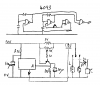
The diagram will be clearer and easier to follow if you put the 0V rail along the bottom and the positive rail across the top. Also, having the relay shown separately adds a lot of unnecessary confusion and opportunity for error.

I would use a grunty N-channel MOSFET instead of a relay. A good choice would be the NTD4906; see http://www.digikey.com/product-detail/en/NTD4906N-35G/NTD4906N-35GOS-ND/2194521

I would sense the light bulb current in the source lead of the MOSFET. This allows you to use a standard single-supply op-amp or comparator to detect the bulb current.

Bulb current will be a lot higher than nominal, and will not accurately reflect the bulbs present, at the start of each flash. You need to sample the bulb current shortly before the end of the flash.

You also need to latch the result of the current comparison somehow, so the oscillator speed will be steadily either slow or fast. The way you've designed it at present, the comparator output will go high and low with the flashing, and this won't give you a steady fast/slow signal to the oscillator.

Your comparator needs to have a reference voltage to compare the shunt resistor drop to. I would use a voltage divider across the supply voltage, because the supply voltage will also affect the bulb current.

You've probably already discovered that connecting the transistor to the 555 in that way doesn't work. There is no simple way to do it, that I know of. My best guess at a possible solution would involve three transistors.

You still haven't given any background information on your project, and you have ignored most of the questions I have asked so far, so I can't make any more specific suggestions.
 

abuhafss

Aug 3, 2010
348
Joined
Aug 3, 2010
Messages
348
First of all, the chip U643B is not available in my area, I have to import it.

I working on an alternate solution which restricts me to the original size of the car flasher. I cannot use MOSFET because the relay clicking sound also reminds the driver that the indicator switch is ON.

As for PICs, I don't have experience programming them.

As for the comparator, yes I am facing some issues. I will work on your advice of reference voltage.
 

duke37

Jan 9, 2011
5,364
Joined
Jan 9, 2011
Messages
5,364
Instead of changig the frequency of the oscillator, you could use two oscillators.
I think a 4093 can do the job as shown. The frequency of an oscillator will be 2.7/(R*C).

The line marked A will be needed to switched from hight to low to change the frequency. A resistor in the output will be needed to detect the current and a transistor and smoothing capacitor to drive point A.

A P channel fet could be used as a switch.
 

Attachments

  • flasher.png
    flasher.png
    3.6 KB · Views: 138

KrisBlueNZ

Sadly passed away in 2015
Nov 28, 2011
8,393
Joined
Nov 28, 2011
Messages
8,393
I don't know what you mean about "U643B". It's not shown on your diagram and I didn't suggest it.

You could use a piezo transducer to make the clicking noise. That would be cheaper and smaller than a relay.

Your best bet is definitely a microcontroller.
 

duke37

Jan 9, 2011
5,364
Joined
Jan 9, 2011
Messages
5,364
And here is the rest of the circuit.
 

Attachments

  • flasher2.png
    flasher2.png
    10 KB · Views: 192

abuhafss

Aug 3, 2010
348
Joined
Aug 3, 2010
Messages
348
I don't know what you mean about "U643B". It's not shown on your diagram and I didn't suggest it.

I already provided you link for that. It is an 8-pin IC specifically made for automotive flashers. That IC is not available here so I am looking for some feasible alternate.
 
Top