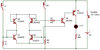
At the start, S1 and S2 are open, Q1-Q4 are off, the base of Q5 is floating so it's off, there is no base current path through Q5 for Q6 so it's off, and the LED is off. For XOR inputs = 0,0, the output is 0.
Note that if there were any Q5 emitter current, it has a two paths to GND, through Q1 and Q2 bases to R1 and R2 to GND.
When S1 closes, Q1 stays off. The Q3 emitter is pulled up above its base, turning it on. S1 current goes around Q4 and into R3, turning on Q5. This turns on Q6 and the LED. The Q76 base current goes through Q5, coming out the emitter, entering the Q2 emitter, going through the Q2 base-emitter junction, coming out the base, and going through R2 to GND.
Follow a similar path for S1 open and S2 closed.
When both switches are closed, both the Q1 and Q2 bases are hard tied to Vcc, turning them off, Now there is no path to GND for the Q6 base current through Q5, So when both switches are closed (XOR inputs equal 1,1), the output is 0.
ak