Hi everyone,
I need some help with my project - did electronics years ago and getting a bit rusty.
So I have this systems monitor from Blue Sea that monitors your batteries and level of liquids in the tanks. Unfortunately, I can't use the sensors that are listed as compatible and the only way I can measure the liquid level is by measuring the hydrostatic pressure at the bottom of the tank.
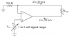
I bought a sensor that outputs voltage depending on the pressure from 0V to about 1.6V for maximum water level in my application. So far so good.
Now, the monitor accepts resistive sensors with the range from 10ohm at minimum level to 180ohm at the maximum level.
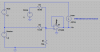
I'm pulling my hair trying to come up with a circuit that could output a resistance as a function of input voltage. I'm sure the answer is simple, but I just can't figure it out!
Please please help!
I need some help with my project - did electronics years ago and getting a bit rusty.
So I have this systems monitor from Blue Sea that monitors your batteries and level of liquids in the tanks. Unfortunately, I can't use the sensors that are listed as compatible and the only way I can measure the liquid level is by measuring the hydrostatic pressure at the bottom of the tank.
I bought a sensor that outputs voltage depending on the pressure from 0V to about 1.6V for maximum water level in my application. So far so good.
Now, the monitor accepts resistive sensors with the range from 10ohm at minimum level to 180ohm at the maximum level.
I'm pulling my hair trying to come up with a circuit that could output a resistance as a function of input voltage. I'm sure the answer is simple, but I just can't figure it out!
Please please help!