Maker Pro
Maker Pro

Transistor instead of relay

h3rman

Mar 30, 2013
4
Joined
Mar 30, 2013
Messages
4
I made a circuit that is supposed to replace a bunch of relays.

Question no 1 - Does this work?

Question no 2 - How can i make an N.C. function? (I cannot use the 60 VDC as power supply)
 

Attachments

  • c1.png
    c1.png
    6.9 KB · Views: 181

KrisBlueNZ

Sadly passed away in 2015
Nov 28, 2011
8,393
Joined
Nov 28, 2011
Messages
8,393
It might work. It depends.

What are the "contacts" being used for? Show the circuit that you will be connecting them to.

How are the "relays" controlled? I don't see any input to the circuit.
 

h3rman

Mar 30, 2013
4
Joined
Mar 30, 2013
Messages
4
Basically the hole thing is just relay and contacts. This circuit is supposed to replace type of relay that the stopped manufacturing many many years ago.

On the load side there is a bunch of regular relay contacts on each side of this circuit and then another relay coil. Positive voltage is coming in on the upper connection and the relay coil and earth is always on the lower.
This circuit uses the 60VDC as input. I should have drawn connections on the input side instead of drawing an battery. The input only got an DC voltage and a bunch of relay contacts in between.

But my real problem is the N.C 'contacts'. Normally i would put an inverter before the optocoupler, but since i got no constant power supply that won't work.
 
Last edited:

KrisBlueNZ

Sadly passed away in 2015
Nov 28, 2011
8,393
Joined
Nov 28, 2011
Messages
8,393
On the load side there is a bunch of regular relay contacts on each side of this circuit and then another relay coil.
You've used all English words there, but I can't make head or tail of it.

Can you post a diagram of the circuitry that you want to connect to the output of the relay?

Re converting the design to normally closed, there may be ways to do this. For example, instead of connecting the optocoupler's transistor between the collector and base of the output transistor, you could connect it between the base and emitter, with a resistor from base to collector. The resistor will turn the transistor ON by default, and energising the optocoupler will force the transistor OFF by removing its bias.

But all of this depends very much on what you want to connect to the collector and emitter of the output transistor. You need to provide a diagram, or at least a clear and detailed description, of how the "contacts" will be used.
 

h3rman

Mar 30, 2013
4
Joined
Mar 30, 2013
Messages
4
Thanks for replaying.

Sorry, english isn't my primary language :)
This circuit is supposed to replace basically any of the contacts is this example.

I tried to draw what you wrote, is that what you mean (the lower one)? Wouldn't that cause current to flow between the connections through the optocoupler?

Edit: added actual example, don't mind the strange contacts they are not drawn in a unenergized state but in it's 'normal state' :p
It's the K+f relay (in this example) i wish to replace.
 

Attachments

  • example.png
    example.png
    5.3 KB · Views: 138
  • version 2.png
    version 2.png
    6.9 KB · Views: 135
  • Skärmavbild 2013-04-01 kl. 09.07.38.png
    Skärmavbild 2013-04-01 kl. 09.07.38.png
    25.7 KB · Views: 152
  • Skärmavbild 2013-04-01 kl. 09.09.37.png
    Skärmavbild 2013-04-01 kl. 09.09.37.png
    53.2 KB · Views: 120
Last edited:

Harald Kapp

Moderator
Moderator
Nov 17, 2011
13,722
Joined
Nov 17, 2011
Messages
13,722
Have a look at solid state relays.
Note that any electronic solution will have a voltage drop that is higher than a pair of good mechanical relay contacts. Your Darlington solution will incur at least 1.3V voltage drop, if not more. It depends on your application whether you can tolerate such.
 

KrisBlueNZ

Sadly passed away in 2015
Nov 28, 2011
8,393
Joined
Nov 28, 2011
Messages
8,393
OK, I see. Thanks for that diagram.

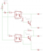
Yes, your modified schematic is what I was suggesting, to convert a normally open circuit to normally closed.

Using an optocoupler driving a transistor is not a perfect solution. As Harald just pointed out, you will have some voltage dropped across the transistor. If you connect several "contacts" in series, these voltage drops will add together, and there may not be enough voltage remaining to activate your final relay coil reliably.

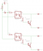
With my suggested normally closed circuit, yes, you will also get some leakage current when the transistor is OFF. Whether this is a problem or not depends on the relay coil that the contacts are driving. A small amount of leakage current won't cause enough voltage across the final relay coil for it to pull in, but it will waste power.

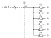
Can you modify the part of the circuit that has the relays connected in series driving another relay? If so, you can replace those relays with optocouplers, connect the optocoupler transistors in series, and use them to switch a transistor that's powered from the 48V supply, which can drive the relay coil. That would be a simpler solution if it's possible to modify the circuit in that way.

If you need a completely self-contained circuit that will plug into any of those positions and replace an old relay, another option might be to use a standard electromechanical relay specified for a lower voltage, and add a resistor in series with the coil so that it will operate from 60V. You should be able to find 48V relays with sensitive coils that could completely replace the original relays. You could get relays with changeover contacts, so you could use the normally open contact or the normally closed contact. This would be your simplest option.
 

h3rman

Mar 30, 2013
4
Joined
Mar 30, 2013
Messages
4
Thanks for your replay. I'm going to ponder a bit about it.
 

duke37

Jan 9, 2011
5,364
Joined
Jan 9, 2011
Messages
5,364
Am I missing something here?
In the original circuit, the optocoupler drives the darlington which drops the collector voltage which turns off the optocoupler. The result is that the circuit will sit halfway turned on. The optocoupler needs to be fed with a constant supply.
 

KrisBlueNZ

Sadly passed away in 2015
Nov 28, 2011
8,393
Joined
Nov 28, 2011
Messages
8,393
You're right, the Darlington won't saturate. Typical Darlington Vbe at moderate current would be 1.5V; add a few hundred mV for the optocoupler's transistor, and a bit more for the voltage dropped across the series resistor. I'd say the voltage drop would be 2~3V. That's why I said that the circuit is not ideal.
 
Top