Derek Filliams
- Nov 30, 2017
- 4
- Joined
- Nov 30, 2017
- Messages
- 4
Hi,
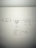
I've been going around in circles trying to control 12V and up to 0.5A with my arduino Mega but can't get any transistor to work correctly. The correct amount of current never passes from collector to emitter (I've been using NPN transistors). I think I maybe have my bjt concepts mixed up. If I am looking to pass 0.5A @12V DC using a 0.04A @ 5v signal, what spec transistor am I looking for?
Thanks,
Derek
")