Maker Pro
Maker Pro

Transformer identification

Markula

Jul 20, 2018
2
Joined
Jul 20, 2018
Messages
2
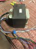
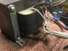
This big boy was pulled from an HP mass-spectrometer. I believe input voltage was 240VAC. I’d like to think I could use it in an audio amplifier or power supply build. Any thoughts on how to discern output voltages? Can I use a 120V input? TIA!
 

Attachments

  • F2781BDB-653E-4966-9522-40406228456F.jpeg
    F2781BDB-653E-4966-9522-40406228456F.jpeg
    347.9 KB · Views: 60
  • FE782035-BA00-46E0-84F7-C9622AA70B05.jpeg
    FE782035-BA00-46E0-84F7-C9622AA70B05.jpeg
    283 KB · Views: 58

duke37

Jan 9, 2011
5,364
Joined
Jan 9, 2011
Messages
5,364
The white wires look to be very thick and is likely to be a low output voltage. Measure the resistances between wires to determine which windings are connected.

The transformer may have twin input windings which can be connected in series for 240V or in parallel for 120V. In any case running a 240V transformer on 120V is OK but the output voltages will be halved.

When you have determined what windings are what, You could energise the highest resistance winding through a lamp limiter to find the voltage ratios. Do not kill yourself.
 

(*steve*)

¡sǝpodᴉʇuɐ ǝɥʇ ɹɐǝɥd
Moderator
Jan 21, 2010
25,510
Joined
Jan 21, 2010
Messages
25,510
Trace back the wires you disconnected to where they came from. Maybe the board will have some useful information about voltages.

Have you checked for a service manual for the mass spectrometer? It may have information about the transformer used.

Was the input voltage on the mass spectrometer variable (i.e. did it have a switch or some other means of setting the input voltage? There may be multiple primary windings which are configured (often dual 120V windings with taps at 100V that are used in various series and parallel combinations to achieve 2 or 4 (sometimes more) input voltage ranges.
 
Top