Maker Pro
Maker Pro

Traffic light sequencer

caveatlector

Nov 2, 2015
3
Joined
Nov 2, 2015
Messages
3
I am as new as one can be to electronics. I know a little of this and that and I can learn easily enough.

So with that in mind I am trying to build a simple traffic light sequencer for my child for a traffic light I am building. It will just be one set of lights--red, yellow, green, to use with a toy motorized jeep.

I got the parts I think I need, including:
A 6" modular IC breadboard socket
555CN Timer IC
1N4148 diodes
resistors: 100k Ohm, 22k Ohm, 330 Ohm
100k Ohm potentiometer (though I don't know if I need a 1m?)
capacitors: 0.1uF, 10uF, 2.2mF
4017 IC counter
I also have 3 separate clusters of LED lights.

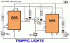
I have found several circuit diagrams on the internet but they are for UK style lights where they cycle red, red+yellow, green, yellow--then back to red where it starts over. Can anyone give advice on how to cycle it in the US style pattern?

Here is the website I was settling on for a diagram but it is the UK style.
http://rookieelectronics.com/sequential-traffic-lights/

Any help is greatly appreciated.
 

KJ6EAD

Aug 13, 2011
1,114
Joined
Aug 13, 2011
Messages
1,114
The schematic for the Velleman MK131 Traffic Light kit uses the pattern you want.

http://www.velleman.eu/downloads/0/minikits/manuals/manual_mk131.pdf

LED colors (Red, Yellow, Green)/directions (North, East, South, West) map as follows:
LD1, G/S; LD2, G/N; LD3, G/W; LD4, G/E; LD5, Y/N; LD6, Y/S; LD7, Y/W; LD8, Y/E; LD9, R/S; LD10, R/N; LD11, R/W; LD12, R/E.
 
Last edited:

Martaine2005

May 12, 2015
4,950
Joined
May 12, 2015
Messages
4,950
Hello Caveatlector,
That should be simple enough to do.
You say you have led clusters? Can you be more specific what you have and how they are connected?
Because you may need a transistor on the outputs to run more leds.
But simply the 4017 has 10 outputs. But not so simply, is the output pins order!
You would think that 1,2,3,4,5 etc would make sense. But oh no. It's 3,2,4,7,10,1,5,6,9,11.
So it's easy to play with the order and timing. If you want red on for 4 counts, use 3,2,4 and 7. Amber for 2 counts use 10 and 1. Then green on for 4 counts use 5,6,9 and 11.
And it's that simple.
All that the other schematic does is turn on two colours at the same time by using a single output via diodes.
Note the diodes are there so as not to short the other outputs.

Martin
 

caveatlector

Nov 2, 2015
3
Joined
Nov 2, 2015
Messages
3
Hello Caveatlector,
That should be simple enough to do.
You say you have led clusters? Can you be more specific what you have and how they are connected?
Because you may need a transistor on the outputs to run more leds.


Martin

Well it's basically the heads of three LED flashlights that have 9 LEDs each.
 

Martaine2005

May 12, 2015
4,950
Joined
May 12, 2015
Messages
4,950
Hello,
can you post a picture of the cluster or tell us what voltage ie batteries were in the torch?
You cannot drive 9 leds from an output without extra components.

Martin
 

caveatlector

Nov 2, 2015
3
Joined
Nov 2, 2015
Messages
3
Hello,
can you post a picture of the cluster or tell us what voltage ie batteries were in the torch?
You cannot drive 9 leds from an output without extra components.

Martin
Each cluster is powered by 3 batteries that are in a series and 1.5v each. So 4.5v for each cluster of LEDs.
 

Martaine2005

May 12, 2015
4,950
Joined
May 12, 2015
Messages
4,950
Hello,
Without knowing how they are wired, I would play safe and use a transistor.
Connect a 1K resistor from the 4017 output to the base of a 2N3904 or similar PNP transistor.
You will probably only have two wires going to the cluster. Find the positive and negative sides of the (cluster), you may be lucky and have red and black wires.
Connect the positive (anode) side of leds to positive rail and and negative (kathode) to the collector of the transistor. And emitter to negative 0v rail.

I doubt the leds (cluster) will need further current limiting.
The only thing left to do is to modify this in order to get the cluster to turn on dersired outputs with desired led cluster.
This can be done easily by adding diodes to the outputs you want to use. (called diode steering).
You can use 1N4148 diodes or similar.

EDIT: You may have to add another battery to allow for diode and transistor diode Vf (forward voltages).
But keep it simple first and add as needed.

Martin
 

CDRIVE

Hauling 10' pipe on a Trek Shift3
May 8, 2012
4,960
Joined
May 8, 2012
Messages
4,960
Well it's basically the heads of three LED flashlights that have 9 LEDs each.
Hello,
can you post a picture of the cluster or tell us what voltage ie batteries were in the torch?
You cannot drive 9 leds from an output without extra components.

Martin
From the description it sounds like the LED flashlight that Horror Freight gives away free with any purchase from them. I have lots of them!
http://www.harborfreight.com/3-12-in-9-led-mini-flashlight-69111.html

Sir Uncle Chris
 
Top