Maker Pro
Maker Pro

traffic light australian with 2 555 timers

stspringer

May 10, 2019
116
Joined
May 10, 2019
Messages
116
Hello all,
Hope someone can help me. I can only get the green led to turn, off and on, the red and yellow stay on constantly. I tried many times to no avail. Does anyone have a link to where I can see the actual wire hook ups? I am a newbie going nuts.

Thanks
 

Attachments

  • traffic light with 2 555 timers australian_2.png
    traffic light with 2 555 timers australian_2.png
    188 KB · Views: 15

AnalogKid

Jun 10, 2015
2,892
Joined
Jun 10, 2015
Messages
2,892
Your question doesn't say *anything* about what it is you are trying to achieve. Please describe the timing sequence in a text table like this:

Red only: x seconds
Red and green: x seconds
Green only : x seconds
Green and yellow: x seconds
Yellow only: x seconds
repeat

Or something like that.

Also, the circuit has some issues. It usually is a bad idea to power one IC from the signal output of another IC. There are other ways to have one 555 control another. Also, the adjustment pots do not have any fixed resistance in series, so adjusting all the way to one end might damage the ICs.

For loooong timing periods like these, it is much better to use the CMOS version of the 555 - LMC555.

ak
 
Last edited:

stspringer

May 10, 2019
116
Joined
May 10, 2019
Messages
116
Your question doesn't say *anything* about what it is you are trying to achieve. Please describe the timing sequence in a text table like this:

Red only: x seconds
Red and green: x seconds
Green only : x seconds
Green and yellow: x seconds
Yellow only: x seconds
repeat

Or something like that.

ak
Sorry, all I have is this schematic which I uploaded. I thought it should work if I hooked up the wires as shown in the schematic.Could you get this to work if all you had was a schematic some one handed to you? Then you would change things perhaps to change the times you mention.Or am I way off base? Australian traffic light goes like this same as the US

red for x time then to green for x time then from green to yellow to warn that red is about to come on then to red. Yellow would be x time also so lets say red for 1 minute green to 2 minutes yellow for 30 seconds back to red for 1 minute

The times are not my concern now I just want to get a red green yellow loop and worry about the times later.

Thanks
 
Last edited:

AnalogKid

Jun 10, 2015
2,892
Joined
Jun 10, 2015
Messages
2,892
"work" is a purely subjective term. If you don't know what the sequence is supposed to be, how can we evaluate why it is not happening?

Let's back up. What is this for? What are you building? Model train set? Science Fair project? Architectural demo?

???

ak
 

AnalogKid

Jun 10, 2015
2,892
Joined
Jun 10, 2015
Messages
2,892
Not all of the components have reference designators, so we need to add some:

Left 555: U1
Right 555: U2
Red LED: D1
Yellow LED: D2
Green LED: D3

With VR1 in the middle of its range, U1 has an output period of approx. 11 seconds. That means D1 is on for 5.5 seconds and off for 5.5 seconds. The intent of the circuit is that D2 and D3 do something during the D1 off time. That gets messy because when a 555 is powered up, the first 1/2 cycle output is not the same as the rest of the cycles.

When U1 provides power to U2, the intent is that D3 comes on immediately. After a time (adjustable by VR2), D3 turns off and D2 turns on. No matter how long those two LED (combined) are on, after 5.5 seconds U1 removes power, both go out, and D1 comes on again.

Red only: 5.5 seconds (adjustable)
Green only: Red period minus Yellow period
Yellow only: Red period minus Green period

Issues. It is possible for the G+Y time to be adjusted longer than the R time. In this case, Y could be adjusted so short tat it never comes on. One thing this circuit can *not* do is have R and G with the same on time and still have Y on for a time. G+Y = R. If Y is on for any time, that time is subtracted from the G time.

Not a great design, but no obvious flaws. If the circuit is not doing this, then you have either a dead chip or wiring errors.

ak
 
Last edited:

stspringer

May 10, 2019
116
Joined
May 10, 2019
Messages
116
"work" is a purely subjective term. If you don't know what the sequence is supposed to be, how can we evaluate why it is not happening?

Let's back up. What is this for? What are you building? Model train set? Science Fair project? Architectural demo?

???

ak
Ok let me explain where I am coming from. I am a total newbie, I am just trying to learn how to transfer from a schematic to a breadboard. I go on the web and find a schematic that looks interesting, and not too complicated for a beginner.
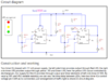
I assume the schematic, in this case a traffic light system for Australia, would do something, if I transfer it to a breadboard.

All I know is that in Australia the traffic light goes from red to green to yellow to red in a loop. I am assuming that is what this schematic is all about.

This is what I am expecting to see if I transfer this schematic to a breadboard. What I get with all my efforts is just green going off and on, after approx 9 seconds, in a loop. Red and yellow are constantly on.

I am expecting to see red on, red off, green on, green off, yellow on, yellow off,red on, red off, back to green and repeat.

So I am assuming, the odds are, that the schematic is correct, and my transfer to breadboard is incorrect.

I hope you understand that I am not concerned about how long eache light stays on at this time. I just know I should see red come on and then go off as green then comes on then green goes off and then yellow comes on and then yellow goes off and then red comes on and so on in a loop. If the schematic does that I can worry about the time duration for each light later.

Thanks
 

AnalogKid

Jun 10, 2015
2,892
Joined
Jun 10, 2015
Messages
2,892
Looks like this one is all on you. The sch is not how I would do it, it does use the Discharge output in a non-standard way to get two switched outputs from one part; not a bad trick.

The only thing missing is decoupling capacitors across the 555 power pins. This is a bit of a problem because the one across U2 will affect its timing, but not critically. Add a 10 uF electrolytic cap in parallel with a 0.1 uF ceramic cap from each 555 Vcc pin to its GND pin. Keep the leads as short as possible. I don't think this will fix your problem, but it is a serious omission from the source schematic.

Where are you located?

ak
 
Last edited:

stspringer

May 10, 2019
116
Joined
May 10, 2019
Messages
116
Looks like this one is all on you. The sch is not how I would do it, but the only thing missing is decoupling capacitors across the 555 power pins. This is a bit of a problem because the one across U2 will affect its timing, but not critically. Add a 10 uF electrolytic cap in parallel with a 0.1 uF ceramic cap from each 555 Vcc pin to its GND pin. Keep the leads as short as possible. I don't think this will fix your problem, but it is a serious omission from the source schematic.

Where are you located?

ak
I am in Buffalo, NY where are you located?

AnalogKid I now you are trying to help, and I appreciate it, but you are going way too deep for me.

The sch is not how I would do it but the only thing missing is decoupling capacitors across the 555 power pins

So you are saying that I found a broken schematic?

Thanks
 

AnalogKid

Jun 10, 2015
2,892
Joined
Jun 10, 2015
Messages
2,892
I fully support your education process. When I was in high school (1960's), all I could get were hand-me-down issues of Popular Electronics. Now, the universe is available, including PDF files of all of the old electronics magazines.
 

stspringer

May 10, 2019
116
Joined
May 10, 2019
Messages
116
I fully support your education process. When I was in high school (1960's), all I could get were hand-me-down issues of Popular Electronics. Now, the universe is available, including PDF files of all of the old electronics magazines.

So you are saying that I found a broken schematic?
 

AnalogKid

Jun 10, 2015
2,892
Joined
Jun 10, 2015
Messages
2,892
I'm saying the schematic is missing important (but not necessarily critical) parts. This is a sign of either an inexperienced designer or one who just forgot them because adding them to the build is automatic for him.

A critical assumption in the design of all integrated circuits is the quality of the power sources to the device. Some demand almost theoretically perfect power - zero ohm source impedance, zero noise, infinite current, perfect regulation, etc. Of course, the real world is not like that. The standard mitigation is to add capacitors across the device to stabilize the power it sees, The caps act as a combination of lowpass noise filter and short-term transient energy reserve. The cap leads should be as short as possible, and connected to the chip Vcc and GND pins as closely as possible.

Because of a quirk in the bipolar 555 chip design (NE555, SE555, LM555, MC555, etc.), its output stage tries to short out the power source for a few nanoseconds each time it transitions from one state to the other. This can cause problems for both the chip itself and surrounding circuits. The added caps are called "decoupling" capacitors because the isolate the chip from whatever nasty crap has happened to the source voltage on its way over from the power supply, and isolate other things on the same power bus from noise injected onto the power bus by the 555.

ak
 

stspringer

May 10, 2019
116
Joined
May 10, 2019
Messages
116
No, I'm saying your problems probably are a wiring error.

ak
Well that was my original assumption. Can you help me figure it out? Can you somehow, in nwebie terms, or a drawing, show me where you would place the wires?

Thanks
 

AnalogKid

Jun 10, 2015
2,892
Joined
Jun 10, 2015
Messages
2,892
Disconnect U2 pin 8. this removes power from U2 and isolates it from U1.

Verify that the U1 part is working correctly:
Disconnect the top of VR1 from U1 pin 3.
Add a 10K resistor in series between U1 pin 3 and the top of VR1.
Adjusting VR1 should vary the red LED timing from about 12 seconds on / 12 seconds off to 2 on / 2 off.

If all of that works, we move on. If it doesn't, beat on it until it does.

For U2:
Add the 10K resistor in series with VR2 as you did with VR1.
Connect U2 pin 8 directly to the +12 V source. Do not connect it as in the schematic.
The Green and Yellow LEDs should toggle back and forth with the same adjustment range.

If not, then describe carefully what is happening. Except for the way the LEDs are connected, the two circuits are identical and should behave the same before they are connected together.

ak
 

Audioguru

Sep 24, 2016
3,656
Joined
Sep 24, 2016
Messages
3,656
The second link in Google Images for Traffic Light Circuit shows the horrible circuit you found. The first link is that circuit as a kit from Arizona, USA. Most of all the other circuits use a 555 as a clock driving a CD4017 counter/divider.

You found a defective circuit from a website in South Asia (?) written by a student (?) with less knowledge about electronics than you. There are many electronic websites like that there.
It shows a simple LM386 audio amplifier circuit also with many errors.
 

Attachments

  • amplifier errors.png
    amplifier errors.png
    38.2 KB · Views: 5

Bluejets

Oct 5, 2014
6,920
Joined
Oct 5, 2014
Messages
6,920
Hello all,
Hope someone can help me. I can only get the green led to turn, off and on, the red and yellow stay on constantly. I tried many times to no avail. Does anyone have a link to where I can see the actual wire hook ups? I am a newbie going nuts.

Thanks

The "secret" to operation of the first circuit is not to have variable resistors in the cap circuit or/ to have them each set to a value as shown in the "Talking electronics" site.
Look under "traffic lights" in the left side panel in the interactive section.

There is a complete explanation there as well.

Edit:- ..... I do believe i have referenced this site to you previously.

Note that there are many circuits there AND complete books one can download for free.
Should keep you going for a while.
I've no doubt then you will latch on to Arduino which will open up different possibilities for you.
Cheers Jorgo
 
Last edited:

stspringer

May 10, 2019
116
Joined
May 10, 2019
Messages
116
The "secret" to operation of the first circuit is not to have variable resistors in the cap circuit or/ to have them each set to a value as shown in the "Talking electronics" site.
Look under "traffic lights" in the left side panel in the interactive section.

There is a complete explanation there as well.

Edit:- ..... I do believe i have referenced this site to you previously.

Note that there are many circuits there AND complete books one can download for free.
Should keep you going for a while.
I've no doubt then you will latch on to Arduino which will open up different possibilities for you.
Cheers Jorgo

Hello Jorgo,
I did go to the site "Talking electronics" I see the schematic with the explanation. Thank you
http://www.talkingelectronics.com/te_interactive_index.html
 

stspringer

May 10, 2019
116
Joined
May 10, 2019
Messages
116
Hello Jorgo,
I did go to the site "Talking electronics" I see the schematic with the explanation. Thank you
http://www.talkingelectronics.com/te_interactive_index.html


So this is the fix right?

Here is a further description of how the circuit works:
Both 555's are wired as oscillators in astable mode and will oscillate ALL THE TIME when they are turned ON. But the second 555 is not turned on all the time!
The first 555 turns on and the 100u is not charged. This makes output pin 3 HIGH and the red LED is not illuminated. However the output feeds the second 555 and it turns on.
Output pin 3 of the second 555 turns on the green LED and the second 100u charges to 2/3 rail voltage and causes the 555 to change states. The green LED goes off and the orange LED turns on.
The second 100u starts to discharge, but the first 100u is charging via a 100k and after the orange LED has been on for a short period of time, the first 555 changes state and pin 3 goes LOW.
This turns on the red LED and turns off the second 555.
The first 100u starts to discharge via the 100k and eventually it changes state to start the cycle again.
The secret of the timing is the long cycle-time of the first 555 due to the 100k and the short cycle due to the 47k on the second 555.
One problem is the timing for the first time the circuit is turned ON is different to the continued operation, because the 100u's have to charge from 0v.
The sequence was not perfect with 100u + 100u so Paul Mathew changed the first 100u to 220u and the sequence was perfect.
You can change the 100k to 220k instead of changing the electrolytic
.
 

stspringer

May 10, 2019
116
Joined
May 10, 2019
Messages
116
The "secret" to operation of the first circuit is not to have variable resistors in the cap circuit or/ to have them each set to a value as shown in the "Talking electronics" site.
Look under "traffic lights" in the left side panel in the interactive section.

There is a complete explanation there as well.

Edit:- ..... I do believe i have referenced this site to you previously.

Note that there are many circuits there AND complete books one can download for free.
Should keep you going for a while.
I've no doubt then you will latch on to Arduino which will open up different possibilities for you.
Cheers Jorgo

So this is the fix right?

Here is a further description of how the circuit works:
Both 555's are wired as oscillators in astable mode and will oscillate ALL THE TIME when they are turned ON. But the second 555 is not turned on all the time!
The first 555 turns on and the 100u is not charged. This makes output pin 3 HIGH and the red LED is not illuminated. However the output feeds the second 555 and it turns on.
Output pin 3 of the second 555 turns on the green LED and the second 100u charges to 2/3 rail voltage and causes the 555 to change states. The green LED goes off and the orange LED turns on.
The second 100u starts to discharge, but the first 100u is charging via a 100k and after the orange LED has been on for a short period of time, the first 555 changes state and pin 3 goes LOW.
This turns on the red LED and turns off the second 555.
The first 100u starts to discharge via the 100k and eventually it changes state to start the cycle again.
The secret of the timing is the long cycle-time of the first 555 due to the 100k and the short cycle due to the 47k on the second 555.
One problem is the timing for the first time the circuit is turned ON is different to the continued operation, because the 100u's have to charge from 0v.
The sequence was not perfect with 100u + 100u so Paul Mathew changed the first 100u to 220u and the sequence was perfect.
You can change the 100k to 220k instead of changing the electrolytic.
 
Top