Sir Ernie1979 . . . . .
" they . . .Just want to charge $1000+"
From what I am seeing of that unit, as being compared to a relative true worth . . . . I hope that those "
ECCLESIASTICALLY accursed " . . . ." maternally copulating " . . . . "
Sweet Ole
Boys " have a 1000 units all tied up in their stock inventory and never sell a single unit, 'til hell freezes over. ! Damn carpetbaggers . . .
I am just making initial minimum changes a la schematic . . . ..
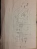
I notice that your +12 power supply buss travels across the very top and then drops down to power the 555 and later the 557 LED driver transistor and FINALLY your having it connected into the GATE ? ? ? ? ? of the IRF44. See if it is not being wired as I have changed it to, on the Source . Since Drain and the heat sink tab are being directly connected.
Yes like my pic not yours.
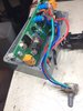
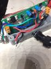
Looking at the whole assembly.. . . .
Am I correctly seeing the RED and BLACK stubbed and tinned wires as being the connections to the pump proper, that would terminate at the nearby YELLOW screw Euro connector.
Yes correct
Meanwhile, the extreme end of the boards 2 pin Euro connector is acccepting the 12VDC power in ?
Yes
Now back to the very slightly revised schema.. . . .
The 555's pin 3 feeds drive to the Z44 base via the RED DOT line path, along the way it drops off at the VIOLET DOT path with base drive for the 557 LED driver transistor. Also the BLUE dot path feeds to the gate of the STP FET, but with those 4-5 band resistors, 10 ohms seems WAY low, so see if you don't need to add a trailing zero or two.
I questioned this too - but it is definitely correct = 10 ohms and meter test reads 10 ohms. (Brown, blk, blk, gold. 100/10=10)
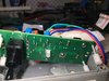
Don't know what the STP does, but since I am NOT physically being able to see your "S/W" at top left corner. NOR its wiring
GAUGE being used.
The big black toggle sw on/off is soldered to the pcb.
Somehow I want to think that the STP is being a power switch, being turned on, into conduction, by a minimally power / current rated "S/W" by establishing its gate drive. .
Pee Ess . . . . . I am experiencing an optical " collusion " . . . of seeing a double stacked STP. Surely that is a mirror polished tin plate on that foil heat sink rectangle, that the STP is screwed down to . . . . and casting a mirrored reflection..
Yep your not loosing it ;-)
***** Also tell me what the the
Yellow / RED LED action light sequences are, under the different situations .********
When the light is Red = 12.45v, light yellow = 13.05v (my battery voltage), hence I believe when yellow it should cut off voltage inorder to stop the pump. With the mian toggle switch OFF, the lights continue to switch but there is 0V at the main output to the pump and hence pump turns off. With switch ON I get the above.
First quick test would be to disconnect from battery and test the ohms reading from D-to S of the 44 and then the STP, with the RED and Black wires still being
UN-connected.. D-S of 44 = 6 Mohm, D-S of STP= Open ALSO, if i test voltage over the 10k and 4.7k resistors it switches from 12.45v to ~1.2v, which is how i expect it to be at the Main Voutput but it is 13.05v.
Now I never have seen an IRF 44, with other than its heat sink tab showing, but the STP might be offered in the same exposed heat sink tab exposed,
BUT ALSO in a polycarbonate case ( insulated) which only lets you make Drain connection to the center leaded terminal.
Use an exposed heat sink tab version and you would have to mica insulate the tab, or get an
UNWANTED SHORT.
PSEUDO RE-REFERENCE . . . . . .
https://i.imgur.com/pnGPDyT.jpg
73's de Edd
.....................
Now, if people EVOLVED from apes, why are there still being apes around ?
")