Hi guys,
First post on this forum - I had a search around but couldn't find what I was looking for.
I'm building a motor controller that consists of a 555 timer configured in astable mode to output a frequency around 6KHz, i'm then feeding this 50% duty cycle PWM signal through an RC integrator to convert it to a triangular waveform.
This is then fed as an input into a comparator, the other input being the output from a pot to allow me to adjust reference voltage, and thus PWM output. The reason I'm doing it in three stages like this is to give me 0-100% PWM as opposed to 10-90% PWM.
A few questions;
I've attached some pictures.
Cheers in advance for any replys!
J
First post on this forum - I had a search around but couldn't find what I was looking for.
I'm building a motor controller that consists of a 555 timer configured in astable mode to output a frequency around 6KHz, i'm then feeding this 50% duty cycle PWM signal through an RC integrator to convert it to a triangular waveform.
This is then fed as an input into a comparator, the other input being the output from a pot to allow me to adjust reference voltage, and thus PWM output. The reason I'm doing it in three stages like this is to give me 0-100% PWM as opposed to 10-90% PWM.
A few questions;
- If i want to replace the pot with a 2 wire thermistor, how would I go about acheiving this? I can't quite work it out. The aim is to make one of the inputs to the comparator temperature dependant.
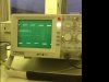
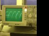
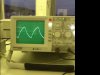
- Secondly, looking at the outputs on a 'scope - the 50% duty cycle PWM signal from the 555 is perfect, as is the triangular waveform. However, the output from the comparator looks like PWM in that I have a high signal, but the low signal is replaced with wha tlooks like the charging of a capacitor? Would maybe adding a diode to the comparator inputs solve this?
I've attached some pictures.
Cheers in advance for any replys!
J