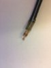
Does anyone know where I can get some of these thermistors of similar value to replace the broken ones we have ? any help appreciated
@kellys_eye provided a
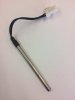
link to a large selection of "bare" thermistors. Your problem is to select one that works for your application and then mount it in the stainless steel tube you showed in your photos, replacing the (apparently) defective one in the photographs.
... is it possible to build our own probes, or does this requires specialist equipment or components ?
Sure, but you need to know two things: the resistance at 25 C and the beta factor to allow you to select a thermistor compatible with your existing control electronics. Ordinary soldering skills are required to attach the thermistor leads to the external wiring before it is inserted (along with the thermistor) inside the stainless steel tube. You can purchase closed-end stainless steel tubes or make your own from tubing stock, maybe even get fancy and heli-arc a small bead on the end to close the tubing. Or just epoxy the thermistor in place.
Thermistors are highly non-linear, but extremely sensitive devices. Knowing their zero-power resistance at 25 C provides just one point on their characteristic curve. Knowing the "beta" factor allows you to determine the resistance at a second, different temperature, although not with very good accuracy (because the curve relating temperature to resistance is, well... curved.) The formula below provides an approximation to the actual curve and is probably "gud enuf" for heating hot water in a drink dispenser:
R(T) = R(To) exp [B (1/T - 1/To)]
Find the above formula at
this Vishay link.
Note the temperature is expressed in degrees Kelvin, so be sure to make the appropriate conversion from Celsius. You should "calibrate" your only working thermistor in boiling water (100 C = 373 K) by measuring its zero-power resistance there and at "room temperature" (25 C = 298 K) and then calculating the value of "B" or beta in the above formula to find a replacement thermistor. It is important to actually measure the zero-power ambient temperature and the zero-power elevated temperature independently with an accurate thermometer, such as a laboratory grade mercury thermometer, because small errors in defining these two zero-power temperatures will show up as errors in the value of B or beta that is calculated using these resistance measurements.
Most modern multimeters will use a constant-current source, typically on the order of one milliampere or less, to measure resistance. Unless your thermistor bead is truly tiny, this small current will not cause any appreciable self-heating of the thermistor and the resistance you measure will be the "zero power" resistance to within a sufficient level of accuracy. You can test this hypothesis by observing the resistance reading after connecting the meter probes to the thermistor: if the resistance starts to noticeably decrease, then self-heating is occurring from the multimeter measuring current. I won't go into any detail about how to avoid that, but basically you would need to reduce the constant-current excitation, which will decrease the voltage measured across the thermistor, and increase the sensitivity of the voltmeter measurement. Be careful not to add your own body heat to the ambient temperature measurement. A glass of water, well stirred, should be used as the ambient temperature reference.
If an accurate thermometer is not available, an ice-water bath (well stirred) can be used as a 0 C reference and boiling water (roiling boil) as a 100 C reference. You can use the resistance measurements at these two temperatures to calculate what the thermistor resistance should be at 25 C, which will then allow you make a selection from a table of available thermistors.
Once you have determined the B or beta value and the 25 C resistance value, find a thermistor from the list of available, off-the-shelf, devices and purchase a half dozen or so. If desired, you can purchase closed-end stainless steel tubes and suitable wire and connectors to pre-assemble the replacement devices.
It would be extremely helpful if you could photograph and describe the electronics the thermistor is connected to. Better yet, part numbers and manufacturer could be helpful. Are you preparing to repair just one drink dispenser, or are there are several that are potentially failing? If the latter, then it is important that you have a robust and inexpensive solution at hand to get them up and running with a minimum of down time.