Maker Pro
Maker Pro

The Trouble with Transistors

aerospace1248

Jan 1, 2013
4
Joined
Jan 1, 2013
Messages
4
As a noob, I know just enough about transistors to get me into trouble, the more I read, the more I don't seem to be able to answer my question myself.

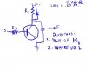
While trying to use an NPN as a switch, I just can't seem to figure out exactly where to connect my relay to the circuit. Maybe my problem is trying to use just one common ground, but I seem to be cutting the switch OUT of the circuit, and thereby rendering it useless. Will some of you smarter kids in the class tell me what I'm doing wrong. I hope the upload looke good

Thanks up front for any and all help.

Thanks much,
joe
 

Attachments

  • s Project.jpg
    s Project.jpg
    40.2 KB · Views: 134

BobK

Jan 5, 2010
7,682
Joined
Jan 5, 2010
Messages
7,682
The relay coil goes where Rc is (that is in place of Rc).

To calculate Rb you start with the desired base current. This the the collector current / beta, because beta is the ratio of collector current to base current. But them multiply this by 2 to make sure the transistor is in full saturation. For example. For a beta of 100 (typical of a 2N3904), and collector current of 250ma, you would get:

Ib = 250 / 100 * 2 = 5ma. So the resistor must drop 4.3V at 5ma.

V = I R
4.3 = 0.005 R
R = 4.3 / 0.005 = 1060. A 1K resistor should do nicely.

Bob
 

Starbuckin

Jan 22, 2013
10
Joined
Jan 22, 2013
Messages
10
Yes, Bob is correct. To use an NPN Transistor as a switch, you want the Transistor to be fully saturated... This means that there is enough DC base to emitter current to cause the Collector and Emitter to become a short circuit.... In other words, imagine that the Collector and Emitter are shorted to each other by a piece of wire. When the Transistor is fully saturated, you can draw a strait line between them on your schematic.

Likewise when there is no Base Emitter current, the Collector - Emitter Junction acts like open air...

Not to get too far ahead for you but of course the Transistor isn't a "perfect" switch. There will be a very small voltage drop across the Collector Emitter Junction when the Transistor is "on"... Likewise there will also be a small current still flowing when the Transistor is off.. It will usually be in Nano Amps so it will not effect your average load...

Also, I notice you have a reverse biased diode across your collector load resistance RC... I'm assuming that you are symbolizing the relay as a load resistor (RC) in your schematic. I wanted to comment that it is VERY important that you not forget to include this diode when you build the circuit. When a relay is switched off the magnetic field around the coil collapses and produces a high voltage in opposite polarity of the voltage across the relay when it is on. This voltage can damage the transistor and ANY other circuitry connected to the same power supply as this circuit.

The reverse biased diode will be forward biased at the instant that the Transistor and Relay cut off and will absorb this voltage, rendering it harmless...
 
Last edited:
Top