Maker Pro
Maker Pro

the circuit not working

walid.anjum

Dec 18, 2013
26
Joined
Dec 18, 2013
Messages
26
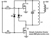
the circuit attched with this message is not working properly so any help from u guys be appreciated
values for the compnents are
supply 15v
r1 and r2 =250ohm 1 watt
d1 and d2 = 1n5819
nchannel mosfet Q1 and Q2 = irfz44
capictor= 0.47micro farad
L1= 1.1 micro H
L2=2.2=nano H
 

Attachments

  • induction ckt.jpg
    induction ckt.jpg
    2.2 KB · Views: 139

(*steve*)

¡sǝpodᴉʇuɐ ǝɥʇ ɹɐǝɥd
Moderator
Jan 21, 2010
25,510
Joined
Jan 21, 2010
Messages
25,510
the image is too small to make out. Can you post a larger one.

It would also help if you described both what it's supposed to do and what it's doing.
 

walid.anjum

Dec 18, 2013
26
Joined
Dec 18, 2013
Messages
26
its an induction heating ckt...i am not able to adjust the size of pic as upload lsize limit is 19.7 kb so it is makng an issue
 

davenn

Moderator
Sep 5, 2009
14,260
Joined
Sep 5, 2009
Messages
14,260
the upload size limit is ~ 100kb much more than the 19kb you said

regardless of that a much larger gif image is only a few kb any way
do a 600 x 400 gif of your circuit

Dave
 

(*steve*)

¡sǝpodᴉʇuɐ ǝɥʇ ɹɐǝɥd
Moderator
Jan 21, 2010
25,510
Joined
Jan 21, 2010
Messages
25,510
its an induction heating ckt...i am not able to adjust the size of pic as upload lsize limit is 19.7 kb so it is makng an issue

That's 97.7k -- save it as a png using paintbrush or similar.

We routinely upload much larger images without a problem.

If you can't do that, upload it to an image hosting site and post a link.
 

walid.anjum

Dec 18, 2013
26
Joined
Dec 18, 2013
Messages
26
chk this circuit plz
 

Attachments

  • induction-heater-schematic.png
    induction-heater-schematic.png
    38.9 KB · Views: 132

(*steve*)

¡sǝpodᴉʇuɐ ǝɥʇ ɹɐǝɥd
Moderator
Jan 21, 2010
25,510
Joined
Jan 21, 2010
Messages
25,510
OK, now we have a circuit large enough to read and a description of what it's supposed to do, what is it doing (or not doing)?
 

jpanhalt

Nov 12, 2013
426
Joined
Nov 12, 2013
Messages
426
Here is a link to the actual project: http://www.rmcybernetics.com/projects/DIY_Devices/diy-induction-heater.htm

There are a lot of comments over about 2 years, and it seems the circuit can be made to work.

First, I second the request to describe what it is and/or isn't doing.

Second, please attach pictures of your project. There is some leeway in construction, but apparently not much.

Third, Did you use exactly the components specified in the original article? If not, what substitutions did you make?

John
 

walid.anjum

Dec 18, 2013
26
Joined
Dec 18, 2013
Messages
26
r1 and r2 =250ohm 1 watt
d1 and d2 = 1n5819
nchannel mosfet Q1 and Q2 = irfz44
capictor= 0.47micro farad
L1= 1.1 micro H
L2=2.2=nano H

this is an induction heating circuit .and the compenents and their spec are given above .the main problem is that its is not generating freq at the output.is thre any simulator which can use to simulate the oscilloscope and giving graph in hertz.thanks
 

(*steve*)

¡sǝpodᴉʇuɐ ǝɥʇ ɹɐǝɥd
Moderator
Jan 21, 2010
25,510
Joined
Jan 21, 2010
Messages
25,510
I believe they say that L2 should be in the region of 1mH, not 1nH -- it needs to be about a million times larger in inductance.

What are the specs for your power supply? What current are you measuring?

What is C1. Is it a single capacitor? They recommend several in parallel to allow for the peak current.

Is anything getting hot?
 

jpanhalt

Nov 12, 2013
426
Joined
Nov 12, 2013
Messages
426
At most, that is 15 mW of power.

What are you trying to heat? I hope its mass is appropriately small. ;) At a ratio of 15W/g, consider that one milligram of air is a little less than 1 mL. The same mass of water is 1 µL.

John
 
Last edited:

(*steve*)

¡sǝpodᴉʇuɐ ǝɥʇ ɹɐǝɥd
Moderator
Jan 21, 2010
25,510
Joined
Jan 21, 2010
Messages
25,510
If it's drawing that little current then I would assume one of the following:

1) you've wired up the mosfets incorrectly.
2) you've killed the mosfets in a way other than internally shorting them.

What is your power supply? (what are its ratings -- maximum current would be a good start).

Can you post a picture of your construction?
 

jpanhalt

Nov 12, 2013
426
Joined
Nov 12, 2013
Messages
426
And it is almost certainly not oscillating.

Can you (walid.anjum) measure and tell us the gate-to-ground and the drain-to-ground voltages across each mosfet?

Please confirm the part number of the mosfets you used.

John
 

walid.anjum

Dec 18, 2013
26
Joined
Dec 18, 2013
Messages
26
its 3.1 volt gate to ground...and 2.84V drain to ground..........and Mosfet model num: IRZ44
 

(*steve*)

¡sǝpodᴉʇuɐ ǝɥʇ ɹɐǝɥd
Moderator
Jan 21, 2010
25,510
Joined
Jan 21, 2010
Messages
25,510
walid.anjum, you need to read all the replies.

The one telling you that one of your inductors is a million times too small is probably worth heeding.
 

jpanhalt

Nov 12, 2013
426
Joined
Nov 12, 2013
Messages
426
IRZ44 is not a mosfet!

Capture.PNG

Do you mean IRFZ44 or IRLZ44 or just i.r. lazy?

Sorry.

John
 

Arouse1973

Adam
Dec 18, 2013
5,178
Joined
Dec 18, 2013
Messages
5,178
I got this working in LT-Spice. Works fine. I think your problem is two things.
1) The inductor value is too low as already mentioned.
2) Putting two inductors together is not the same as having one inductor and trying to connect to the centre. You need to have mutual inductance between the inductor for this to work. Make sure the coils wound dot marking follows each other.
Adam
 
Top