DeadReanimation
- May 4, 2010
- 2
- Joined
- May 4, 2010
- Messages
- 2
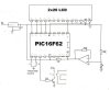
hello. im trying to make a temperature control system that uses a PIC16F627 with assembler code.
The attachment show is my circuit. using a voltage regulator to keep the LCD display at +5 volts.
When it his the temperature desired it turns on a fan (next to the relay and the transistor).
when booted up initially i want it to start at 30 degrees Celsius for the temp of turn on. but the two switches with plus and minus on them to vary the thermostat control.
the voltage and current at 40 degrees is 2.54v & 482 uA. (u = micro)
while at 6 degrees it's: 4v & 124 uA
my system was based on the circuit that was on the website below. my system however uses a thermistor. but it appears it has been replaced with a dual temp sensor and no thermostat control so figure two is the diagram that used to be there
electronics-diy.com/pic_temperature_meter
i would appreciate it if people gave me help on how to do the code in assembler as im a novice in code.
Attachments

Last edited: