Maker Pro
Maker Pro

Technics Receiver SA-600 Repair

amonarch71

Aug 27, 2018
10
Joined
Aug 27, 2018
Messages
10
I have been working on this receiver for a while now. I bought it from ebay as damaged/ for parts status. I replaced a couple
of transistors and I also replaced to two main drivers.

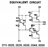
When I got the receiver only one channel was working and I tested some voltage nodes on the main Darlington Power Transistor for the left and the right channel. One of the Darlington channels had high voltage(15 volts approx.) readings while the other Darlington Power Transistor measured in 20 mV.

Unfortunately I had to make pilot holes with a fine wire drill bit to identify the solder side of the pcb board to unsolder and replace
the correct component which at the time was measured as being dysfunctional with the DMM.

I was able to correctly to replace the dysfunctional components but severed some of the traces with the bit. I decided to solder some jumpers to bypass the severed traces. Just recently I was testing the traces and one of them was contacting a node with was accidently made.

I believe this might have been the cause of the sparks while testing with a volt meter but I am not exactly sure.

Thanks
 

Attachments

  • Darlington.jpg
    Darlington.jpg
    121.4 KB · Views: 43
  • Jumpers Technics.jpg
    Jumpers Technics.jpg
    188.6 KB · Views: 46
  • Transistor 2 uncomfirmed.jpg
    Transistor 2 uncomfirmed.jpg
    195.5 KB · Views: 41
  • Transistor one uncomfirmed.jpg
    Transistor one uncomfirmed.jpg
    206.5 KB · Views: 45

kellys_eye

Jun 25, 2010
6,514
Joined
Jun 25, 2010
Messages
6,514
Fix those wire links for starters. Horrendous repair practice..... the bare ends are far too long and exposed and a source for potential short circuits.

Testing semiconductors in-circuit doesn't always work.

Do you have the schematic for the device?
 

amonarch71

Aug 27, 2018
10
Joined
Aug 27, 2018
Messages
10
Yes I do have a schematic. The model is a Technics sa-300. I have a pdf document of that receiver and the pdf contains a schematic. Thank you for the critic. I am need all the advice I can get.

As far as the pilot holes, is there a better way to locate the component on the other side of the PCB? I tried to eye ball it but I was not very successful in identifying the component on the other side of the board. That is why I drilled the holes which obviously caused other problems i.e. soldering the jumpers which I have learned is bad practice.

Thanks
I can't upload the pdf file with the schematic. I can try to render the pages into a jpg of the 2 pages that contain the schematic or you can google it online and download it.
 

kellys_eye

Jun 25, 2010
6,514
Joined
Jun 25, 2010
Messages
6,514
You should be able to post he PDF here as an attachment. Do you have a link to it online somewhere?

Repeated ''flipping' of the board is the usual method to locate parts - just takes practise.
 

amonarch71

Aug 27, 2018
10
Joined
Aug 27, 2018
Messages
10
I rendered the schematic from the pdf into separate jpg files. The pdf file is too large and flagged an error every time I tried to upload it to this website. The unit we are discussing about is a Technics sa-300. The posted name of the receiver is not the correct model number, however these schematics are correct with the model number Technics sa-300.

If you know of a way to reduce the file size of the pdf manual for the Technics sa-300 please let me know. I tried compressing it into a zip file and that did not work. There are options to reduce the file size however I must have a premium subscription to adobe reader which requires an annual fee.
 

Attachments

  • tech sch 1.jpg
    tech sch 1.jpg
    165.3 KB · Views: 27
  • tech sch 1a.jpg
    tech sch 1a.jpg
    112.4 KB · Views: 27
  • tech sch 2.jpg
    tech sch 2.jpg
    171.6 KB · Views: 26
  • tech sch 2a.jpg
    tech sch 2a.jpg
    129 KB · Views: 27

kellys_eye

Jun 25, 2010
6,514
Joined
Jun 25, 2010
Messages
6,514
Do you have ONE channel working?

Have you checked the fuses and the output of the power supply?
 

kellys_eye

Jun 25, 2010
6,514
Joined
Jun 25, 2010
Messages
6,514
Power supply output? What voltage do you read?

If it is 'good' then you can compare voltages between channels at strategic points and note the discrepancies between the working and non-working channel.
 

amonarch71

Aug 27, 2018
10
Joined
Aug 27, 2018
Messages
10
Power supply output? What voltage do you read?

If it is 'good' then you can compare voltages between channels at strategic points and note the discrepancies between the working and non-working channel.

The last time I checked to voltage after replacing the power transistors. I had the same results with headphones with only one channel working. I was measuring one of the stk0039 transistor with a volt meter and it sparked at the node. I just it off and then connected speakers to the receiver. I got a loud hum on both speakers, so neither channel works now. I was not expecting the spark, and I took a break from fixing it and later blew a fuse using the Voltage Meter.

I am very concerned what my risks are and whether or not to even continue pursuing to make this repair.

I am hesitant to powering it up and after replacing the power fuse. I have a variac and I am wondering if
it will be beneficial in this repair application
 

kellys_eye

Jun 25, 2010
6,514
Joined
Jun 25, 2010
Messages
6,514
Making sparks and blowing fuses whilst taking test measurements just tells me that you don't have the requisite skills to affect a repair and you're more likely to create other problems as a result of your 'poking around'.

No 'measurement' (if taken properly) will cause a spark or blow a fuse - such events usually happen when the user leaves the meter in its current measurement mode!

If you want to continue then you need to read, learn and understand the circuit operation (study the schematic) then PLAN where to take test measurements and act on the results. Basic meter use skills are, of course, essential. Do you have those skills?
 

amonarch71

Aug 27, 2018
10
Joined
Aug 27, 2018
Messages
10
Making sparks and blowing fuses whilst taking test measurements just tells me that you don't have the requisite skills to affect a repair and you're more likely to create other problems as a result of your 'poking around'.

No 'measurement' (if taken properly) will cause a spark or blow a fuse - such events usually happen when the user leaves the meter in its current measurement mode!

If you want to continue then you need to read, learn and understand the circuit operation (study the schematic) then PLAN where to take test measurements and act on the results. Basic meter use skills are, of course, essential. Do you have those skills?

I do have the skills. In the past I have successfully fixed vacuum tube amplifiers. I also was trained in college how to read schematics, build circuits from schematics, and I am trained in using DMM, oscilloscopes, function generators, etc. I have been fixing tube amps for almost 10 years and I have a B.S. in EET. And I have a strong knowledge base in Electronics Theory. I have spent many years studying amplifier theory, and I can read a schematic and build a circuit straight from the schematic. I learned these skills in college, as well as high mathematic studies and I have some practical experience over the last 10 years.

I have always had difficulty repairing solid state devices
 

kellys_eye

Jun 25, 2010
6,514
Joined
Jun 25, 2010
Messages
6,514
I was measuring one of the stk0039 transistor with a volt meter and it sparked at the node. I just it off and then connected speakers to the receiver. I got a loud hum on both speakers, so neither channel works now. I was not expecting the spark, and I took a break from fixing it and later blew a fuse using the Voltage Meter.


No 'measurement' (if taken properly) will cause a spark or blow a fuse
Just to re-iterate....

My bold

But that aside..... if you have two channels (one working) then comparisons are straightforward. If you've blown the 'other' channel by 'accidental' methods then you've got bigger issues that may require the schematic to resolve. Can you provide a link to the download source for the schematic? It's not easy to read the ones you posted.

The problem is likely to boil down to the 'darlingtons' (which aren't really such but a more integrated version of the principle) and if you have to replace them the cost may outweigh the advantages.
 
Top