Maker Pro
Maker Pro

System reset circuit help please

Danno

Aug 31, 2015
65
Joined
Aug 31, 2015
Messages
65
Hi,
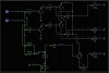
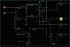
I am trying to understand the purpose of the 3 diodes D27, D28 & D29. Terminals B1, B2, C3, C4 C5 &C6 are feeds out to equipment, these feeds are switched on or of via the 4099 latch.
PN15 goes off to activate a SCR which when activated discharges the capacitor on a 555 timer reset circuit which resets the system.

Could anybody shed some light on how these diodes work to reset the system?

Many thanks.
 

Attachments

  • Snap 2015-09-01 at 08.13.56.png
    Snap 2015-09-01 at 08.13.56.png
    848 KB · Views: 106

(*steve*)

¡sǝpodᴉʇuɐ ǝɥʇ ɹɐǝɥd
Moderator
Jan 21, 2010
25,510
Joined
Jan 21, 2010
Messages
25,510
pn15 will be pulled high unless either pin 13 or 14 of the upper 4099 are low.
 

Danno

Aug 31, 2015
65
Joined
Aug 31, 2015
Messages
65
So if 13 & 14 are high the current path will be through R75 & D29 but if either 13 or 14 go low then the current goes though R75 and either D27 or D28? Is thast correct?

Thanks
 

Harald Kapp

Moderator
Moderator
Nov 17, 2011
13,720
Joined
Nov 17, 2011
Messages
13,720
So if 13 & 14 are high the current path will be through R75 & D29 but if either 13 or 14 go low then the current goes though R75 and either D27 or D28? Is thast correct?
Not quite. It is IC4.13 OR IC4.14, not AND (&). In consequence the voltage at the anode of D29 will be low which in turn may trigger a reset, depending on the circuit that is attached to PN15.

This type of circuit is an AND gate in diode logic.
 

(*steve*)

¡sǝpodᴉʇuɐ ǝɥʇ ɹɐǝɥd
Moderator
Jan 21, 2010
25,510
Joined
Jan 21, 2010
Messages
25,510
So if 13 & 14 are high the current path will be through R75 & D29 but if either 13 or 14 go low then the current goes though R75 and either D27 or D28? Is thast correct?

Thanks

yes ;)

you and I were talking about the output of the 4099 using inverted logic. In this case it's an OR.

if you use normal logic -- which Herald did-- then it's an AND.

it's also important to note that the output is not high or low, it is high or open.
 

Old Steve

Jul 23, 2015
734
Joined
Jul 23, 2015
Messages
734
Thanks for clarifying that point, Steve. I thought that Danno was correct, but didn't want to step on Harald's toes (again). :)
 

Old Steve

Jul 23, 2015
734
Joined
Jul 23, 2015
Messages
734
No problem Harald.
This is a good illustration that a positive logic AND is also a negative logic OR. I just did a quick drawing for Danno's benefit:-

Positive vs Negative logic.JPG
 

Danno

Aug 31, 2015
65
Joined
Aug 31, 2015
Messages
65
Thank you guys that makes sense now, so in this application then would you say that C5 & C6 are critical outputs and if the supply on either of these two is lost then PN15 becomes positive and sends a signal to the reset circuit.
 

Harald Kapp

Moderator
Moderator
Nov 17, 2011
13,720
Joined
Nov 17, 2011
Messages
13,720
The 4099 is a latch. The state of C5 or C6 (pins 13 and 14 of IC4) is controlled by what's written into the latch. PN15, your presumed system reset is controlled by PN15=IC4.13 AND IC4.14 (high active logic). here are two possibilities:
  1. PN15 is active high, then it will be active only if both IC4.13 AND IC4.14 are high.
  2. PN15 is active low (or high impedance due to D29), then it will be active if any of IC4.13 OR IC4.14 is low.
if the supply on either of these two is lost then PN15 becomes positive and sends a signal to the reset circuit.
The supply cannot be lost of either of these two pins alone, only if the supply to IC4 is lost. In that case IC4.13 and IV4.14 will have an undefined state. The voltage on the anode of D29 will probably be around 1.4V which is low in a 5V system.
Why 1.4V, you ask? The IC's output canot drive actively high or low without supply voltage. Without output drive. the 5V on R75 will drive a current through D27/D28 into the protection diodes of each IC4.13 and IC4.14. This currrent will develop a voltage drop of 0.7V across each diode which adds up to 1.4V at the anode on D29.
BUT: If power is lost to IC4, why should there be 5V on R75? Typically the complete 5V supply is lost and the circuit is out of operation.

Then again I may have misinterpreted your reference to "supply is lost".
 

Old Steve

Jul 23, 2015
734
Joined
Jul 23, 2015
Messages
734
It's interesting, (to me at least), that an SCR is used to discharge the capacitor on a 555 to reset the circuit, rather than simply pulling the Reset pin low.
Edit: I can answer my own question - the 555 operates as a high-current-output inverter. When the cap is discharged, the output goes high, not low as I was thinking.
(I could have just deleted my post, but decided it was better to leave it.)
 
Last edited:

Danno

Aug 31, 2015
65
Joined
Aug 31, 2015
Messages
65
It's interesting, (to me at least), that an SCR is used to discharge the capacitor on a 555 to reset the circuit, rather than simply pulling the Reset pin low.


There is also a Omron G2E relay which is used to discharge it
 

Old Steve

Jul 23, 2015
734
Joined
Jul 23, 2015
Messages
734
Obviously there's more going on there than I thought.
Anyway, sorry to go off-topic. :rolleyes:
 

Danno

Aug 31, 2015
65
Joined
Aug 31, 2015
Messages
65
Obviously there's more going on there than I thought.
Anyway, sorry to go off-topic. :rolleyes:

No need to apologize it's all interesting stuff,

The system reset is done via a 555 timer, things that can cause a reset include aerial spark detection circuit (3 transistors), reset trigger from the 4099 as we are discussing, these activate a SCR to discharge the capacitor, there is also the loss of 12Vdc which holds in the G2E relay, if the 12Vdc is lost then the capacitor discharges through the N/C contact.
 

Old Steve

Jul 23, 2015
734
Joined
Jul 23, 2015
Messages
734
No need to apologize it's all interesting stuff,

The system reset is done via a 555 timer, things that can cause a reset include aerial spark detection circuit (3 transistors), reset trigger from the 4099 as we are discussing, these activate a SCR to discharge the capacitor, there is also the loss of 12Vdc which holds in the G2E relay, if the 12Vdc is lost then the capacitor discharges through the N/C contact.
Thanks for that. Very interesting. So, I must ask - what is it?
 

Old Steve

Jul 23, 2015
734
Joined
Jul 23, 2015
Messages
734
Thanks Danno - here in OZ they're mainly called slot machines, but sometimes one-arm bandits.
 

Danno

Aug 31, 2015
65
Joined
Aug 31, 2015
Messages
65
OK I kinda got how this works now, I've run it through a simulator, with pin 13 logic 1 the corresponding light lights through G5, same with G6. If both 13 & 14 are logic 1 then both lights light on G5 & G6 AND the light which simulates the reset circuit lights simulating a reset trigger.

All I have to do know is work out why they would want to reset the system if both these outputs are at logic 1.
 

Attachments

  • Snap 2015-09-02 at 13.32.34.png
    Snap 2015-09-02 at 13.32.34.png
    64.4 KB · Views: 70
  • Snap 2015-09-02 at 13.34.03.png
    Snap 2015-09-02 at 13.34.03.png
    71.3 KB · Views: 72
  • Snap 2015-09-02 at 13.34.20.png
    Snap 2015-09-02 at 13.34.20.png
    86 KB · Views: 70

Old Steve

Jul 23, 2015
734
Joined
Jul 23, 2015
Messages
734
OK I kinda got how this works now, I've run it through a simulator, with pin 13 logic 1 the corresponding light lights through G5, same with G6. If both 13 & 14 are logic 1 then both lights light on G5 & G6 AND the light which simulates the reset circuit lights simulating a reset trigger.

All I have to do know is work out why they would want to reset the system if both these outputs are at logic 1.
It could be that only one or the other is usually high, and that tying the reset to both going high was just a simple way to achieve a reset without additional circuitry.
 
Top