Maker Pro
Maker Pro

Switching loads using Raspberry Pi

Stese

Dec 27, 2013
27
Joined
Dec 27, 2013
Messages
27
Hi All,

I'm starting to get into projects where I need to switch loads on an off, using a Raspberry Pi.

The Pi can only handle a few mA at 3v3, so as projects get larger, I need to isolate the switching from the power. The general way of doing this, as I understand it, is to use NPN Transistors.

Can you look at the simple diagram, and tell me if I've understood how to use transistors in this way, correctly?

Regards,

Steve

Edit - sorry for poor title, I should know better (has been changed by admin/mod)
 

Attachments

  • npn.PNG
    npn.PNG
    2.7 KB · Views: 158
Last edited:

KrisBlueNZ

Sadly passed away in 2015
Nov 28, 2011
8,393
Joined
Nov 28, 2011
Messages
8,393
What you have there is an emitter follower. The emitter will "follow" the base voltage, with a voltage drop of about 0.7V. So when the base is at +3V, the emitter will be at about +2.3V, which may not be enough to light the LED.

The normal way to drive an LED is using a common emitter saturated switch. The general design is:

Driving a LED.GIF

The bottom rail, marked "0V rail", is the common "0V" ("zero volt") reference rail, also sometimes called GND, from the Arduino. The negative side of the 12V battery also connects to this rail.

The control signal from the Arduino enters at the left. When it is high (i.e. at some positive voltage, typically 3.0V, 3.3V, or 5.0V), current flows through RB into the base-emitter junction of Q1, and this turns it ON, i.e. makes it conduct current through its collector-emitter path.

Current then flows from the positive terminal of the battery, through the LED, through the resistor called RLED, through the transistor and back to the battery. This current illuminates the LED.

The LED current (which determines the LED brightness) is set by RLED. You calculate it using Ohm's Law (I = V / R), rearranged:
R = V / I
where
R is the desired resistance for RLED, in ohms (Ω);
V is the voltage across RLED, in volts - this is roughly equal to the supply voltage minus the LED's forward voltage;
I is the desired LED current, in amps.

Say you want to run the LED at 20 mA, and it has a typical forward voltage of 2V at 20 mA. (The forward voltage should be specified on the LED's data sheet; it's typically about 2V for red and green LEDs, a bit higher for yellow, and higher again for blue and white.)

V = (12V - 2V) = 10V
I = 0.02 amps (20 mA is 0.02 amps)
so:
R = V / I
= 10 / 0.02
= 500Ω.

You would use a close preferred value such as 470Ω, 510Ω, or 560Ω.

RBE is optional and seldom needed. It can be helpful if the driving signal doesn't go all the way down to 0V when it's low, or if you want the transistor to turn off extra quickly.

The circuit as shown is fine for driving LEDs. You can replace the LED and its series resistor with other types of low-current loads (the transistors listed can carry up to around 100 mA) but if the load is inductive - a relay coil, for example - you need to reverse-connect a diode across it, to absorb the high-voltage spike that an inductive load will generate when the transistor turns OFF.

You can just use 10 kΩ for RB in most cases. If you want to calculate an ideal value, or learn more about the circuit, Steve (a different one) has written a resource giving more details about common emitter saturated switches at https://www.electronicspoint.com/resources/using-a-bipolar-transistor-to-turn-a-load-on-and-off.30/
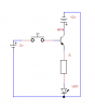
 

Stese

Dec 27, 2013
27
Joined
Dec 27, 2013
Messages
27
Thanks Kris,

I think I understand the difference, (even if I don't understand why it's different!) so I should now be able to kludge something together when required.

Regards.

Steve
 

KrisBlueNZ

Sadly passed away in 2015
Nov 28, 2011
8,393
Joined
Nov 28, 2011
Messages
8,393
Cool :)

The emitter follower (aka common collector) and the common emitter configurations actually use the transistor in quite different ways. Each one has advantages, but when you want to switch a higher voltage with a lower voltage, the common emitter saturated switch is the configuration to use.
 

Stese

Dec 27, 2013
27
Joined
Dec 27, 2013
Messages
27
Am I correct in saying the only difference between the two is the resistor on the Base, or have I missed something?
 

KrisBlueNZ

Sadly passed away in 2015
Nov 28, 2011
8,393
Joined
Nov 28, 2011
Messages
8,393
You have missed LOTS of things!

I can't get into it right now. But Google "common emitter" and "common collector" and learn how both configurations work. They both use a bipolar junction transistor, but that's about the only thing they have in common!
 

Stese

Dec 27, 2013
27
Joined
Dec 27, 2013
Messages
27
Thanks both for the pointers... I do struggle with the more technical bits of this... there is loads to take in and understand! I'll do some reading, and come back if I have any more follow up questions.
 

BobK

Jan 5, 2010
7,682
Joined
Jan 5, 2010
Messages
7,682
An interesting question is why nearly every beginner seems to come up with the emitter follower configuration when first trying to use a BJT as a switch. My guess is that they have a notion that a switch is something that switches the power on an off, and therefore it should be between the + power lead and the load. No one naturally thinks of having the + lead always connected to the load and switching the ground.

Bob
 

Gryd3

Jun 25, 2014
4,098
Joined
Jun 25, 2014
Messages
4,098
An interesting question is why nearly every beginner seems to come up with the emitter follower configuration when first trying to use a BJT as a switch. My guess is that they have a notion that a switch is something that switches the power on an off, and therefore it should be between the + power lead and the load. No one naturally thinks of having the + lead always connected to the load and switching the ground.

Bob
Depends on the application and the thought process I guess...
If I were to build an automotive circuit, I would like to switch the + lead instead of having my device floating at 12+V. My logic behind this is to help prevent shorts to the chassis.
While thinking about it though... If I switched a faulty + lead that was shorted to ground, I could damage the output of the device doing the switching... If I switched a faulty - lead it would not cause any damage. (But would result in the circuit being active until a fuse blows or the fault is resolved.
 

KrisBlueNZ

Sadly passed away in 2015
Nov 28, 2011
8,393
Joined
Nov 28, 2011
Messages
8,393
An interesting question is why nearly every beginner seems to come up with the emitter follower configuration when first trying to use a BJT as a switch. My guess is that they have a notion that a switch is something that switches the power on an off, and therefore it should be between the + power lead and the load. No one naturally thinks of having the + lead always connected to the load and switching the ground.
That's an interesting thought Bob. I haven't really noticed beginners often doing that, but I agree it's the natural way to look at it.

Perhaps some manufacturer should create a two-transistor, four-terminal device like this:
transwitch.gif
 

Stese

Dec 27, 2013
27
Joined
Dec 27, 2013
Messages
27
I think it is exactly how you state Bobk.

Having a basic understanding how electricity works, I think in circles, and thus automatically place switches before the object I want control. I know it will work either way, but it's how I approach it logically., not knowing workings behind a transistor, I didn't realise the effect of the location of the load in relation to the transistor.

Kris, Do you think these are similar in principal to the circuit above? http://uk.rs-online.com/web/p/solid-state-relays/8277090/
 

KrisBlueNZ

Sadly passed away in 2015
Nov 28, 2011
8,393
Joined
Nov 28, 2011
Messages
8,393
Kris, Do you think these are similar in principal to the circuit above? http://uk.rs-online.com/web/p/solid-state-relays/8277090/
No. Solid state relays have full isolation between the control pins and the "contact" pins, just like a normal relay does. That one is rated for 2500V AC isolation.

Also those ones have zero crossing switching, and use an SCR as the control device. This means they are only designed to switch AC, not DC. They would be used to control line-powered motors, heating elements, high-power lamps, that kind of thing.
 
Top