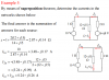
Hey guys, running through an example on superposition but have struck a little hiccup. Have attached the sheet of workings as given out by my lecturer, I understand it up to the i2a calculation, but I cant get my head around why i1a is being multiplied by what seems to be half the equation for the parallel resistors. Would this not give a voltage value? Have been scratching my head at this for the past 20 minutes so thought I would check in and see if it just a stupid mistake I have made or am just missing something.
Cheers for the help guys!
Cheers for the help guys!