Maker Pro
Maker Pro

Solar phone charger (no output!!)

Lawrence1986

Apr 29, 2014
2
Joined
Apr 29, 2014
Messages
2
Hi,

Before I explain my problem I should probably say that I'm only starting out with electronics so I apologise now for any mistakes or inaccuracies within my post.

The Project:

I've got four 5.5v 180mA solar panels. These all have blocking diodes soldered onto them. They are connected up in series. When tested with a multimeter all 4 produce around 7.5v indoors.

I connect them to a 7805ct 5v regulator (http://cgi.ebay.co.uk/ws/eBayISAPI.dll?ViewItem&item=191152529292)

The solar panels are connected to the input and the ground pin goes back to the solar panels - connection.

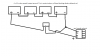
When testing them with the multimeter the input of the regulator shows around 2.5v and the output shows 0v. But when I disconnect the panels they still read about 7v so I know they are generating enough voltage. I've also connected a female usb port to test which is shown in the image file attached.

Ive also tested the voltage regulator using my switch mode power supply and on this it functions correctly and drops voltage from 7 or 12 volt down to 5v.

Any help would be greatly appreciated.


Regards,
Lawrence
 

Attachments

  • solar charger circuit.png
    solar charger circuit.png
    18.2 KB · Views: 117
Last edited:

Harald Kapp

Moderator
Moderator
Nov 17, 2011
13,738
Joined
Nov 17, 2011
Messages
13,738
Hello Lawrence, welcome to our forum.

The schematic looks mainly correct (with exemptions, see below #1). Two ideas come to my mind:
  1. Do you have the blocking capacitors in place as recommended by the datasheet (page 7, figure 1)?
  2. How do the panels behave when loaded? Put an ammeter in series with the panels and use a variable resistor as return to close the circuit. Measure the output voltage of the panels for different currents. Indoors your panels may not generate enough power to drive the regulator (it uses from 4-8 mA by itself).
  3. Measure the current from the panels to the regulator in your original setup. Do you have an oscilloscope to watch the waveform of the voltage? It should be DC but the regulator (without its capacitors) may oscillate. If you don't have an oscilloscope, use the AC millivolt range of your multimeter.
 

(*steve*)

¡sǝpodᴉʇuɐ ǝɥʇ ɹɐǝɥd
Moderator
Jan 21, 2010
25,510
Joined
Jan 21, 2010
Messages
25,510
The blocking diodes (presumably in series) will be reducing your output voltage be up to 4V (under heavy load) or closer to 2V under a small load.

For series connected panels with no other power source you can remove them (or just keep 1).

Try taking the panels outside into the sun. You're not illuminating them enough.

The panels will generate a voltage that falls when a load is placed on it. Even the regulator alone is such a load. When they're generating more power, the voltage drop will be far less (and maybe they;ll generate up to 30V connected like this. If so, the regulator might get quite hot under load as it wastes probably close to 80% of the power.

You might like to consider a series/parallel arrangement of the panels. This would supply twice the current at half the voltage (say 10 to 15V).
 

davenn

Moderator
Sep 5, 2009
14,263
Joined
Sep 5, 2009
Messages
14,263
as Steve hinted
You cant use them indoors, unless under STRONG light

It mite read 7V but will be at pretty much 0A ( zero Amps),as you try to connect a load ... the 7805 ... the voltage WILL DROP because there is no current capability

The 7805 needs a minimum of 7V into it
 

Lawrence1986

Apr 29, 2014
2
Joined
Apr 29, 2014
Messages
2
Thanks a lot for the responses. Lots of things to try now.

Steve do you think the blocking capacitors in that data sheet will be essential as the tutorials I've been looking at only seem to suggest using diodes to stop flow back into the panel. Maybe I can get away without them? I've took your advice and picked up a variable resistor (hopefully 10k is about right??). I'll test this next week when I have more time though.

Thanks for the info guys. I've got diodes on each panel so I'll remove them all except one to stop some of the voltage drop. When simply placing my multimeter on the panel however with a diode connected the voltage is the same as when no diode is there. Would that be because its not in circuit with a load then I presume?

thanks,
Lawrence
 

Harald Kapp

Moderator
Moderator
Nov 17, 2011
13,738
Joined
Nov 17, 2011
Messages
13,738
Without a load (a multimeter is no load) no current flows and the voltage drop across the diodes is very small. That's why I suggested taking the characteristic V versus I of the panels.

The blocking capacitors for the 7805 should be used, even if the circuit seemingly works without them. They are required for stability and quality of the output voltage.
 

(*steve*)

¡sǝpodᴉʇuɐ ǝɥʇ ɹɐǝɥd
Moderator
Jan 21, 2010
25,510
Joined
Jan 21, 2010
Messages
25,510
Steve do you think the blocking capacitors in that data sheet will be essential as the tutorials I've been looking at only seem to suggest using diodes to stop flow back into the panel.

Are you referring to the 7805 datasheet?

There are no blocking capacitors there. There may be input and output capacitance, and yes, I would stick to at least the minimum recommended by the datasheet. Larger input capacitors will allow your power supply to provide brief peaks of current larger than the solar panels can do continuously, and so may be to some advantage.

Maybe I can get away without them?

They're cheap and they can be essential. Don't.

I've took your advice and picked up a variable resistor (hopefully 10k is about right??). I'll test this next week when I have more time though.

My advice? Are you sure?

I've got diodes on each panel so I'll remove them all except one to stop some of the voltage drop. When simply placing my multimeter on the panel however with a diode connected the voltage is the same as when no diode is there. Would that be because its not in circuit with a load then I presume?

You need to show us how the diodes are connected. I have assumed they're in series (which stops power feeding back into the panels) however they could also be in parallel (which assists if one panel is shaded).
 
Top