Maker Pro
Maker Pro

Solar panel measure circuit.

Fai99

Nov 23, 2019
3
Joined
Nov 23, 2019
Messages
3
Hello everyone,

I'm a third year electronics engineering, and I have a project to measure solar power from a solar panel. And when I was searching about a circuit i found this one.

cct.jpg

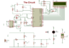
The designer made a voltage divider to measure voltage and another circuit to measure the current.
Then they connected to an A/D converter then sends the data to microcontroller to display these measures.

My question is can you explain the current part measuring? Because I tried to figure this out and I couldn't.

[Mod Edit to put the circuit inline]
 
Last edited by a moderator:

Bluejets

Oct 5, 2014
6,926
Joined
Oct 5, 2014
Messages
6,926
Current flowing through the first group of resistors creates a voltage on each resistor, this is tapped and adjusted output for uC input at whatever level required.
 

Harald Kapp

Moderator
Moderator
Nov 17, 2011
13,722
Joined
Nov 17, 2011
Messages
13,722
Where did you find that circuit (link?) Was there no explanation on that site?
Which of the resistors (R3, R4) is the load?

This circuit looks horribly inefficient with regard to measuring current. The resistor values given will dissipate a lot of the PC's energy as heat.

Have a look here. Remove the current control (X2, Q1). Insert the load instead of Q1. Measure the voltage across R4 as a proxy for the load current. If the voltage drop across R4 is too small, amplify it with a simplke opamp circuit.
Instead of the PC running Labview you can simply attach any multimeter of voltmeter available as long as the range fits the measured values.

BTW: This is a study project and as such I will move it to the homework section.
 

majoco

Nov 10, 2019
50
Joined
Nov 10, 2019
Messages
50
But a 1N4733 is a 5.1volt zener diode - but if there's 12 volts across the two resistors then there's only 2.11 volts across the zener? That circuit will work to measure the voltage but I would have preferred a 10:1 divider or something like that - maybe the zener is there for protection?
Where is the load? Surely that's what you want to measure the current into, or do you want to measure the current coming out of (and back into) the solar cell. A 1 ohm resistor in series at the cell negative terminal will do fine - just measure the volts across it.
 
Last edited:

Fai99

Nov 23, 2019
3
Joined
Nov 23, 2019
Messages
3
But a 1N4733 is a 5.1volt zener diode - but if there's 12 volts across the two resistors then there's only 2.11 volts across the zener? That circuit will work to measure the voltage but I would have preferred a 10:1 divider or something like that - maybe the zener is there for protection?
Where is the load? Surely that's what you want to measure the current into, or do you want to measure the current coming out of (and back into) the solar cell. A 1 ohm resistor in series at the cell negative terminal will do fine - just measure the volts across it.

Thank you guys for your advices but I use this circuit for measuring and monitoring the values, I use a pcf8951 ADC, and as you all know this ADC's maximum supply voltage is 6V, and i use a +5V dc as a reference.
 

Harald Kapp

Moderator
Moderator
Nov 17, 2011
13,722
Joined
Nov 17, 2011
Messages
13,722
I use this circuit for measuring and monitoring the values,
We understand (I think) that part of your request. But we do not understand where in your circuit the load is and the load current, respectively. My guess is you don't know either and that is why nobody can explain the circuit.
The designer made a voltage divider to measure voltage
That part is easy and the comments made so far apply, including the reference to the zener diode as protection of the voltage measuring device which is not shown in the diagram and which you revealed to us as being an ADC. All is good here.
another circuit to measure the current.
Here is where trouble starts. As long as you cant't show where the load current flows, we can't explain how it is measured.
As shown the tap of the 10 k potentiometer gives a fraction of the voltage across R4 and by V=R*I this voltage can be a proxy for the current flowing through R4. Neglecting the resistance of the potentiometer the load would be the series connection of R3 and R4. If that is the case in your setup, then all is well.
If your load is different, the circuit you copied makes no sense for your application. In that case go back to my post #3 and read the linked article. Apply the changes I suggested and you're good. As a 3rd year student of electronics you should be able to do that. If you have doubts, present your self designed circuit for further discussion.
 

Fai99

Nov 23, 2019
3
Joined
Nov 23, 2019
Messages
3
This is the final circuit I use for the project
 

Attachments

  • stmsp pdf2-1.png
    stmsp pdf2-1.png
    386.2 KB · Views: 9

Harald Kapp

Moderator
Moderator
Nov 17, 2011
13,722
Joined
Nov 17, 2011
Messages
13,722
I'm sorry, but this circuit still does not show where the load is. Therefore your original question about current measurement cannot be answered.
 
Top