Maker Pro
Maker Pro

Simple resistor overheat problem

KostasGreco

Jan 24, 2017
14
Joined
Jan 24, 2017
Messages
14
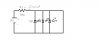
Hi, I have made the simple LED circuit in the picture and my problem is that the current that the led's draw is 100mA. The reristor is having a voltage of 5.3V leading to wattege of 0.53 watts, thus overheating the resistor. I am completely new to electronics.

I have draw the led's diodes in reverse sorry !
 

Attachments

  • Χωρίς τίτλο.png
    Χωρίς τίτλο.png
    19.6 KB · Views: 79

CDRIVE

Hauling 10' pipe on a Trek Shift3
May 8, 2012
4,960
Joined
May 8, 2012
Messages
4,960
Your LED's should be wired in series not parallel. Subsequent to doing so you must recalculate for the proper value of 'R' to produce 100mA.

Chris
 

KostasGreco

Jan 24, 2017
14
Joined
Jan 24, 2017
Messages
14
Your LED's should be wired in series not parallel. Subsequent to doing so you must recalculate for the proper value of 'R' to produce 100mA.

Chris
But in series theres gonna be voltage drops accross every LED ,dimming the light each time.Thats why i did it in parallel in the first place.
 

Chemelec

Jul 12, 2016
291
Joined
Jul 12, 2016
Messages
291
In Parallel like you put them, The 3 LED's will Not Draw the Same Current, Due to slight Variations in each one.
 

KostasGreco

Jan 24, 2017
14
Joined
Jan 24, 2017
Messages
14
In Parallel like you put them, The 3 LED's will Not Draw the Same Current, Due to slight Variations in each one.
yeah but isnt that a very small amount that can be overlooked for three leds? roughly about 33.3 mA /per led?
 

Chemelec

Jul 12, 2016
291
Joined
Jul 12, 2016
Messages
291
It Could actually result in Considerable current differences.
It is Recommended to use a Separate resistor for each one, Or connect them in a Series string with a suitable supply voltage.
 

CDRIVE

Hauling 10' pipe on a Trek Shift3
May 8, 2012
4,960
Joined
May 8, 2012
Messages
4,960
But in series theres gonna be voltage drops accross every LED ,dimming the light each time.Thats why i did it in parallel in the first place.
No, with the proper limiting resistor each LED will still pass equal current when wired in series. It's also more energy efficient because much less power is wasted being dissipated in the resistor. In your case, ...multiple resistors when parallel wired .

Chris
 
Last edited:

CDRIVE

Hauling 10' pipe on a Trek Shift3
May 8, 2012
4,960
Joined
May 8, 2012
Messages
4,960
yeah but isnt that a very small amount that can be overlooked for three leds? roughly about 33.3 mA /per led?
I thought you had high power LEDs. Which is why I mentioned 100mA. I thought I read that in your first post. For common GP LEDs you should run them at 20mA for max longevity.

Chris
 

Audioguru

Sep 24, 2016
3,656
Joined
Sep 24, 2016
Messages
3,656
LEDs have a range of forward voltage. White and blue LEDs are from 3V to 3.6V. The average is 3.3V but all yours might be 3.0V or 3.6V. If you connect 3.0V and 3.6V LEDs in parallel then the 3.0V LED will hog all the current and be destroyed.

If you connect three 3.6V LEDs in series then a 9V battery will not light them and even if you have only two 3.6V LEDs in series then the battery voltage will quickly drop to 7.2V and not light them soon. Use a series resistor for each LED.

How did you make the calculation error with the 550 ohms resistor? If the battery is 9.0V and the LEDs are 3.3V then the 5.7V/550 ohms= 10.4mA which is only about 3.5mA in each LED and the resistor heats with 0.06W.

Why did you select 100mA or 33.3mA each? The absolute maximum allowed continuous current in an ordinary 5mm diameter LED is 30mA.
If the battery is brand new at 9.6V and the LEDs are 3.0V then for 30mA each the resistor value will be (9.6V - 3.0V)/30mA= 220 ohms. If the resistor value is 5% low then it will be 209 ohms and the current will be 31.6mA. It heats with 0.21W.

If the battery drops to 6V, the LEDs are 3.6V and the 220 ohm resistor value is 5% high then the current in each resistor and in each LED will be only 10.4mA.
 

KostasGreco

Jan 24, 2017
14
Joined
Jan 24, 2017
Messages
14
LEDs have a range of forward voltage. White and blue LEDs are from 3V to 3.6V. The average is 3.3V but all yours might be 3.0V or 3.6V. If you connect 3.0V and 3.6V LEDs in parallel then the 3.0V LED will hog all the current and be destroyed.

If you connect three 3.6V LEDs in series then a 9V battery will not light them and even if you have only two 3.6V LEDs in series then the battery voltage will quickly drop to 7.2V and not light them soon. Use a series resistor for each LED.

How did you make the calculation error with the 550 ohms resistor? If the battery is 9.0V and the LEDs are 3.3V then the 5.7V/550 ohms= 10.4mA which is only about 3.5mA in each LED and the resistor heats with 0.06W.

Why did you select 100mA or 33.3mA each? The absolute maximum allowed continuous current in an ordinary 5mm diameter LED is 30mA.
If the battery is brand new at 9.6V and the LEDs are 3.0V then for 30mA each the resistor value will be (9.6V - 3.0V)/30mA= 220 ohms. If the resistor value is 5% low then it will be 209 ohms and the current will be 31.6mA. It heats with 0.21W.

If the battery drops to 6V, the LEDs are 3.6V and the 220 ohm resistor value is 5% high then the current in each resistor and in each LED will be only 10.4mA.
its not 550 ohms. its 55 !
 

Audioguru

Sep 24, 2016
3,656
Joined
Sep 24, 2016
Messages
3,656
its not 550 ohms. its 55 !
Then why did you scribble "550"? if you use Paint program to make the schematic then you can clearly type words.

Did you look at the datasheet for your LEDs and see that their absolute maximum continuous current is only 30mA?
Here is part of the datasheet of a typical 5mm red LED:
 

Attachments

  • red LED.png
    red LED.png
    12.5 KB · Views: 66

Chemelec

Jul 12, 2016
291
Joined
Jul 12, 2016
Messages
291
I think he put 55 o
The o Representing OHMS.

And his plan was Each LED would get 33 mA.

But NOT a Good way to do this!
 

Audioguru

Sep 24, 2016
3,656
Joined
Sep 24, 2016
Messages
3,656
I found strings of LEDs thrown out because they were poorly made and had intermittent connections. All the LEDs were in parallel and somebody must have bought millions of them, tested all of them and grouped them into piles that had exactly the same forward voltage. So I did the same when I built some LED lights and each LED is the same brightness as the others.

Just now I opened a package of LEDs and measured the forward voltage of 10 of them. Two pairs had the same voltages and the rest had voltages fairly different. I am using a separate series resistor for each LED in my new project.
 

KostasGreco

Jan 24, 2017
14
Joined
Jan 24, 2017
Messages
14
Then why did you scribble "550"? if you use Paint program to make the schematic then you can clearly type words.

Did you look at the datasheet for your LEDs and see that their absolute maximum continuous current is only 30mA?
Here is part of the datasheet of a typical 5mm red LED:
ITs 55 Ω omega . greek simbol for ohms.sorry i have never talked in english about electricity before.
 

Audioguru

Sep 24, 2016
3,656
Joined
Sep 24, 2016
Messages
3,656
I did not see the symbol for Ohm:
 

Attachments

  • Ohm.png
    Ohm.png
    4.5 KB · Views: 59

Chemelec

Jul 12, 2016
291
Joined
Jul 12, 2016
Messages
291
He Did an Underlined o ( o ) To Represent the Omega Symbol.

Keyboards do not have that proper Omega symbol
 

CDRIVE

Hauling 10' pipe on a Trek Shift3
May 8, 2012
4,960
Joined
May 8, 2012
Messages
4,960
This Ω symbol was generated by holding down the ALT key and pressing 234 on the number pad (not the number keys below the function keys) found on most keyboards.

Chris
 
Top