Karthik rajagopal
- May 9, 2016
- 257
- Joined
- May 9, 2016
- Messages
- 257
Hi all,
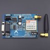
I started working with my project which requires the use of SIM900A. My code gets executed with arduino and GSM without any problem. But I will be using a 3.3V microcontroller whose I/O pins are not 5v tolerant. I am using a SIM900A GSM shield from Astar. I did some continuity test on the board to find out two MOSFETs connected to the Rx and the Tx pins in the configuration I have shown below(the same was for Rx also).

I thought this could be a level shifter but none of the circuits for a level shifter that I found on internet matched with this...all had their souce and gate connected. Will it be safe to connect my GSM directly to the MCU?
I also tried connecting the Tx pin of the GSM to the MCU through a voltage divider,but it did not work.
Please help.
Thanks in advance.
I started working with my project which requires the use of SIM900A. My code gets executed with arduino and GSM without any problem. But I will be using a 3.3V microcontroller whose I/O pins are not 5v tolerant. I am using a SIM900A GSM shield from Astar. I did some continuity test on the board to find out two MOSFETs connected to the Rx and the Tx pins in the configuration I have shown below(the same was for Rx also).
I thought this could be a level shifter but none of the circuits for a level shifter that I found on internet matched with this...all had their souce and gate connected. Will it be safe to connect my GSM directly to the MCU?
I also tried connecting the Tx pin of the GSM to the MCU through a voltage divider,but it did not work.
Please help.
Thanks in advance.