Maker Pro
Maker Pro

Servo Tester Issue

JinTaurus

Dec 2, 2018
8
Joined
Dec 2, 2018
Messages
8
Hello,

I'm new to the forums and I was looking for some advice. I recently acquired a CCPM servo consistency tester and I tried it out on two MG996R servos but something isn't going right. Instead of being able to switch modes on the servo tester all three LEDs just light up and blink and the servos just run odd. In pulses. I know it's not supposed to behave this way.

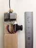
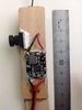
My guess is one of two things: They are digital servos so the tester is having issues with them or it's the way I'm powering the tester. I've included a picture to show my setup. Am I doing this right or do I need to power the servo tester directly and not use any type of power board/bridge?

As is before connecting a servo:
20181202_100817.jpg

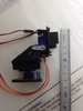
Blinking lights when the servo is connected:
20181202_101845.jpg

Any input is appreciated.
 

kellys_eye

Jun 25, 2010
6,514
Joined
Jun 25, 2010
Messages
6,514
What is the maximum current deliverable by the power supply board?

What is the minimum current the servo needs to operate correctly?
 

JinTaurus

Dec 2, 2018
8
Joined
Dec 2, 2018
Messages
8
What is the maximum current deliverable by the power supply board?

What is the minimum current the servo needs to operate correctly?

The maximum is 5v with the setup shown.

This servo operates at minimum 4.8v up to 6v.
 
Last edited:

Bluejets

Oct 5, 2014
6,920
Joined
Oct 5, 2014
Messages
6,920
Chuck the power module, same with the breadboard and connect 4 x 1.5v AA cells into the tester.
Neither of the 2 dumped items were ever designed to run servos.
 

Bluejets

Oct 5, 2014
6,920
Joined
Oct 5, 2014
Messages
6,920
The servo will at times draw nearer to 1 amp.

The above suggestion was to eliminate the obvious and work your way back.(if you must but be warned it will return to bite you)
 

JinTaurus

Dec 2, 2018
8
Joined
Dec 2, 2018
Messages
8
Chuck the power module, same with the breadboard and connect 4 x 1.5v AA cells into the tester.
Neither of the 2 dumped items were ever designed to run servos.

I've also try running power from this:
20181202_171914.jpg

But got the same result.

I dont own a 4 AA battery holder but I'll get one. It seems power is the issue. I just dont understand why the breadboard can't run it.
 

JinTaurus

Dec 2, 2018
8
Joined
Dec 2, 2018
Messages
8
Well the 4AA battery holder solved the issue. Now I'm dissapointed that my servos turn about 120° instead of 180°. Oh well, they are designed more for torque and that's what I need.

Thanks everyone for your input and help
 

Bluejets

Oct 5, 2014
6,920
Joined
Oct 5, 2014
Messages
6,920
Now I'm dissapointed that my servos turn about 120° instead of 180°

You will find 99.9% of servos are designed for 60 degrees each way.

Reason for the travel is down to 2 facts.
The signal range is from 1mS to 2mS and the internal feedback pot mostly has some form of mechanical stopper to protect the innards.
Both can be overcome by careful (sometimes) modding the pot. Signal can be easy to change if you are providing it.
If it is provided by say an RC unit, then there are travel adjustments but they may be limited.

Other than that, there are 180 degree servos out there.
Link................https://www.banggood.com/buy/180-degree-servo.html
 

JinTaurus

Dec 2, 2018
8
Joined
Dec 2, 2018
Messages
8
Well to be accurate the servos move 140° which serve my purpose well. The plan is to create a pan and tilt with a camera module to track movement.

I am familiar with the pots that limit movement as well as the signal range. I dont feel that I'll need to alter the pots for my purpose.

If you have a good recommendation on a camera module I'd love to hear it. I have a few in mind and I'm trying to stay away from webcams. Keep in mind I'm using the beaglebone black wireless to be the brains behind this project.
 

Bluejets

Oct 5, 2014
6,920
Joined
Oct 5, 2014
Messages
6,920
Well to be accurate the servos move 140°

Yes, well, it IS a $7.00 servo after all.

I dont feel that I'll need to alter the pots for my purpose.

For future reference, one does not alter the pot. Merely check that at the full range of the mechanical stops allows 180 degrees.
The travel is taken care of by extending the signal mS range slightly.

The plan is to create a pan and tilt with a camera module to track movement.

Depends on what your application is exactly.
As an example I built a pan/tilt system here for FPV on the RC glider which monitors the movement of one's goggles. Headtracker unit and also uses a small ( really small) 170 degree camera fed to a 40 channel tx/rx. Good for the kids. It's almost like being in the cockpit (allbeit only around 100 metres range)
Not my idea, just an example of what is available these days. Total there was around $50.00.

There are pan tilt systems that use dedicated stepper motors and really flash control systems. Give expected improved results so worth it if you want that sort of thing I guess.

Couple of photos of the first camera setup on a pod with the 40 channel transmitter on one side and a voltage regulator on the other. Plugs into the main 11.7v flight battery

Second set is a $4.00 pan/tilt unit from Hobbyking with a couple of 9 gm servos. Used as a test unit for the headtracker.
 

Attachments

  • IMG_9227.jpg
    IMG_9227.jpg
    134.9 KB · Views: 2
  • IMG_9228.jpg
    IMG_9228.jpg
    104.8 KB · Views: 2
  • IMG_9229.jpg
    IMG_9229.jpg
    133.3 KB · Views: 2
Last edited:

kellys_eye

Jun 25, 2010
6,514
Joined
Jun 25, 2010
Messages
6,514
Any lack of movement of the servo could be catered for in a suitably pinioned lever arrangement to increase the physical movement.
 

Bluejets

Oct 5, 2014
6,920
Joined
Oct 5, 2014
Messages
6,920
Any lack of movement of the servo could be catered for in a suitably pinioned lever arrangement to increase the physical movement.

Think he requires circular travel distance as in "panning" where the servo is an intrigual part of the gimbal.
 
Top